Rtd module communications setup procedure, Procedure 1, Rtd module – Basler Electric BE1-11m User Manual
Page 512: Pc be1-11 m rtd module
500
9424200996 Rev L
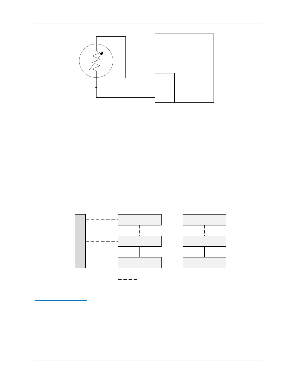
Figure 319. External Three-Wire RTD Input Connections
RTD Module Communications Setup Procedure
Communication between the BE1-11m and the RTD module can be accomplished via Ethernet or
RS-485. Initial settings for the RTD module must be made via Ethernet.
An IP address is assigned to the RTD module in all cases even if the connection between the RTD
module and the BE1-11m will be RS-485. Assigning an IP address to the RTD module gives the user the
option to save a settings file and to view the serial number and firmware version of the RTD module using
BESTCOMSPlus.
Perform one of the following procedures to set up the RTD module.
Procedure 1
The PC and BE1-11m are connected through a network or the PC is connected directly to the BE1-11m
via Ethernet cable or USB cable. The RTD module connects to the BE1-11m via Ethernet or RS-485. See
Figure 320.
Figure 320. Procedure 1
Connect to RTD Module
1.
Connect an Ethernet cable directly between the PC and RTD module.
2.
Apply operating power to the RTD module.
3.
Determine the IP address, Subnet Mask, and Default Gateway of the PC Ethernet port for later use.
Open a Windows
® command prompt by clicking Start Run. Type “cmd”, and click OK. Type
“ipconfig” and press enter.
4.
Record the IP address, Subnet Mask, and Default Gateway of the PC Ethernet port that is connected
to the RTD module. Close the Windows command prompt window.
RTD1+
RTD1–
RTD1C
RTD Module
P
0
0
6
1
-4
1
RED
BLACK
BLACK
N
e
t
w
o
r
k
PC
BE1-11m
RTD Module
Ethernet
Ethernet
P
0
0
6
1
-8
5
RS-485
Ethernet
= Optional
OR
PC
BE1-11m
RTD Module
Ethernet
USB
RTD Module
BE1-11m