Offline logic simulator, Figure 206 – Basler Electric BE1-11m User Manual
Page 265
9424200996 Rev L
253
Next, open the Components tab inside the BESTlogicPlus window and drag a timer onto the program
grid. Right click on the timer to select the timer you want to use that was previously set on the Logic
Timers tree branch. The Logic Timer Properties Dialog Box will appear. Select the timer you want to use.
Timing accuracy is
±15 milliseconds.
Figure 206. Pickup and Dropout Timer Logic Blocks
Offline Logic Simulator
The offline logic simulator allows you to change the state of various logic elements to illustrate how that
state travels through the system. Before running the logic simulator, you must click the Save button on the
BESTlogicPlus toolbar to save the logic to memory. Changes to the logic (other than changing the state)
are disabled when the simulator is enabled. Colors are selected by clicking the Options button on the
BESTlogicPlus toolbar. By default, Logic 0 is red and Logic 1 is green. Using your mouse, double-click on
a logic element to change its state.
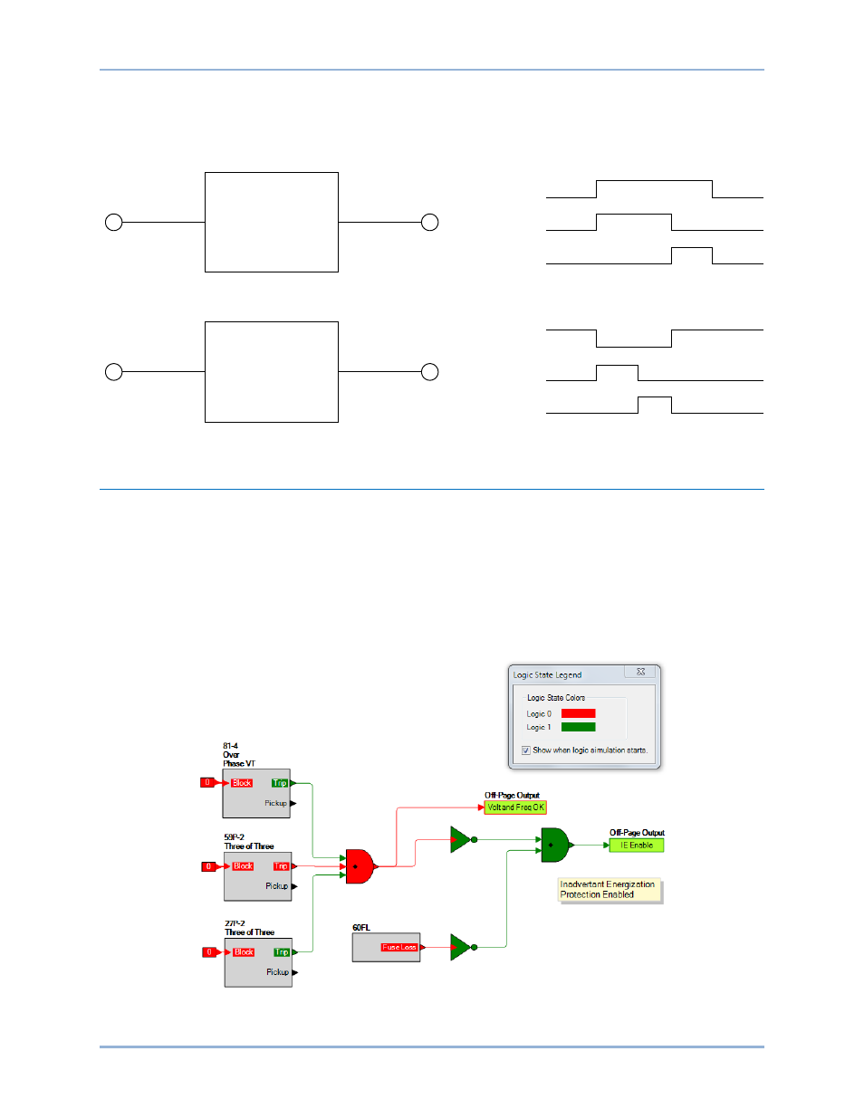
An example of the offline logic simulator is shown in Figure 207. Output 1 is Logic 0 (red) when Input 1 is
Logic 0 (red) and Fixed 1 is Logic 1 (green).
Figure 207. Offline Logic Simulator Example
Initiate
Pickup Time
Output
Initiate
Dropout Time
Output
Pickup
Timer
Dropout
Timer
Output
Output
Initiate
Initiate
P0048-03
BE1-11m
BESTlogic
™Plus