Basler Electric BE1-11m User Manual
Page 563
9424200996 Rev L
551
𝑃𝑖𝑐𝑘𝑢𝑝 = 1.7 𝐷𝐶 𝑂𝑓𝑓𝑠𝑒𝑡 ∙ (125% 𝑜𝑓 𝐿𝑅𝐴 + 2% 𝑃𝑖𝑐𝑘𝑢𝑝 𝑇𝑜𝑙𝑒𝑟𝑎𝑛𝑐𝑒) ∙ 𝑀𝑎𝑥 𝐿𝑜𝑐𝑘𝑒𝑑 𝑅𝑜𝑡𝑜𝑟 𝐶𝑢𝑟𝑟𝑒𝑛𝑡 ∙
1
𝐶𝑇𝑅
= 1.7 ∙ (1.25 + 0.02) ∙ 755 𝐴 ∙
1
60 = 27.17 𝐴 𝑠𝑒𝑐𝑜𝑛𝑑𝑎𝑟𝑦
Equation 63. 50-1 Pickup
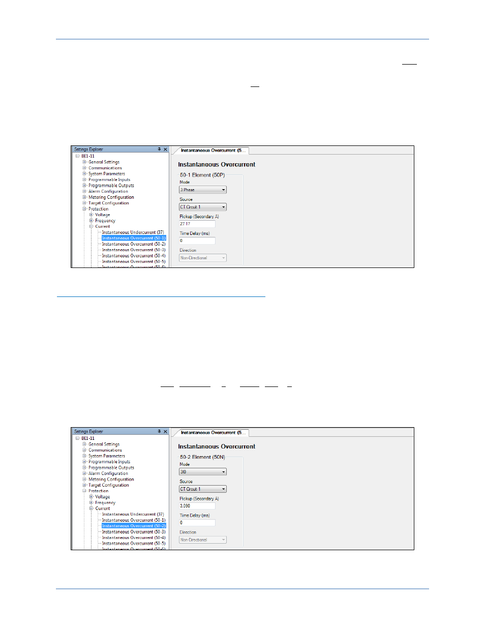
Set for three-phase mode so that any phase exceeding the setting will pick up the element. Set the
Pickup setting to 27.17 A. Typically, CT circuit 1 is used because it is on the feed side of the motor. See
Figure 383.
Figure 383. Protection, Current, Instantaneous Overcurrent (50-1) Screen
Instantaneous Overcurrent (50-2) - Ground Fault Protection
The system is solidly grounded so that a ground fault draws current in the magnitude of a three-phase
fault per IEEE C37.96-2000, IEEE Guide for AC Motor Protection. To determine the three-phase fault
current, consider that the motor subtransient reactance of 0.368 is the limiting impedance. The pickup
setting is calculated using Equation 64. A pickup setting of 1/3 of the instantaneous three-phase fault
current is recommended per IEEE C37.96-2000, IEEE Guide for AC Motor Protection. During starting, CT
saturation can produce false residual currents, so we use the running mode current FLA. The circuit CT
ratio (CTR) is 60.
𝑃𝑖𝑐𝑘𝑢𝑝 = �
1
𝑋"𝑑
∙
𝐹𝐿𝐴
𝐶𝑇 𝑅𝑎𝑡𝑖𝑜� ∙
1
3 = �
1
0.368 ∙
205
60 � ∙
1
3 = 3.09 𝐴 𝑠𝑒𝑐𝑜𝑛𝑑𝑎𝑟𝑦
Equation 64. 50-2 Pickup
Select 3I0 (residual) mode and set the Pickup setting to 3.09 A as shown in Figure 384.
Figure 384. Protection, Current, Instantaneous Overcurrent (50-2) Screen
BE1-11m
Settings Calculation Examples