Basler Electric BE1-11m User Manual
Page 404
392
9424200996 Rev L
Setting
Value
BESTCOMSPlus Screen
Description
Full Load Amps
2
System Parameters, Motor
Configuration
Sets Full Load Amps to 3
Service Factor
1
System Parameters, Motor
Configuration
Sets Service Factor to 1
Element Mode
Standard
Curve
Protection, Thermal, Thermal
Curve (49TC)
Selects Standard Curve
mode
Standard Curve Time
Dial
10
Protection, Thermal, Thermal
Curve (49TC)
Sets Standard Curve Time
Dial to 10
K
0
Protection, Thermal, Thermal
Curve (49TC)
Sets K to 0
Overload
1
Protection, Thermal, Thermal
Curve (49TC)
Sets Overload pickup to 1
Max Emergency
Thermal Capacity
0
Protection, Thermal, Thermal
Curve (49TC)
Sets Max Emergency
Thermal Capacity to 0%
Running Cool Time
Constant
1
Protection, Thermal, Thermal
Curve (49TC)
Sets Running Cool Time
Constant to 1 minute
Stopped Cool Time
Constant
1
Protection, Thermal, Thermal
Curve (49TC)
Sets Stopped Cool Time
Constant to 1 minute
Hot Safe Stall Time
1
Protection, Thermal, Thermal
Curve (49TC)
Sets Hot Safe Stall Time to 1
second
Cold Safe Stall Time
1
Protection, Thermal, Thermal
Curve (49TC)
Sets Cold Safe Stall Time to
1 second
49TC
Enabled
Target Configuration, Targets
Enables 49TC target
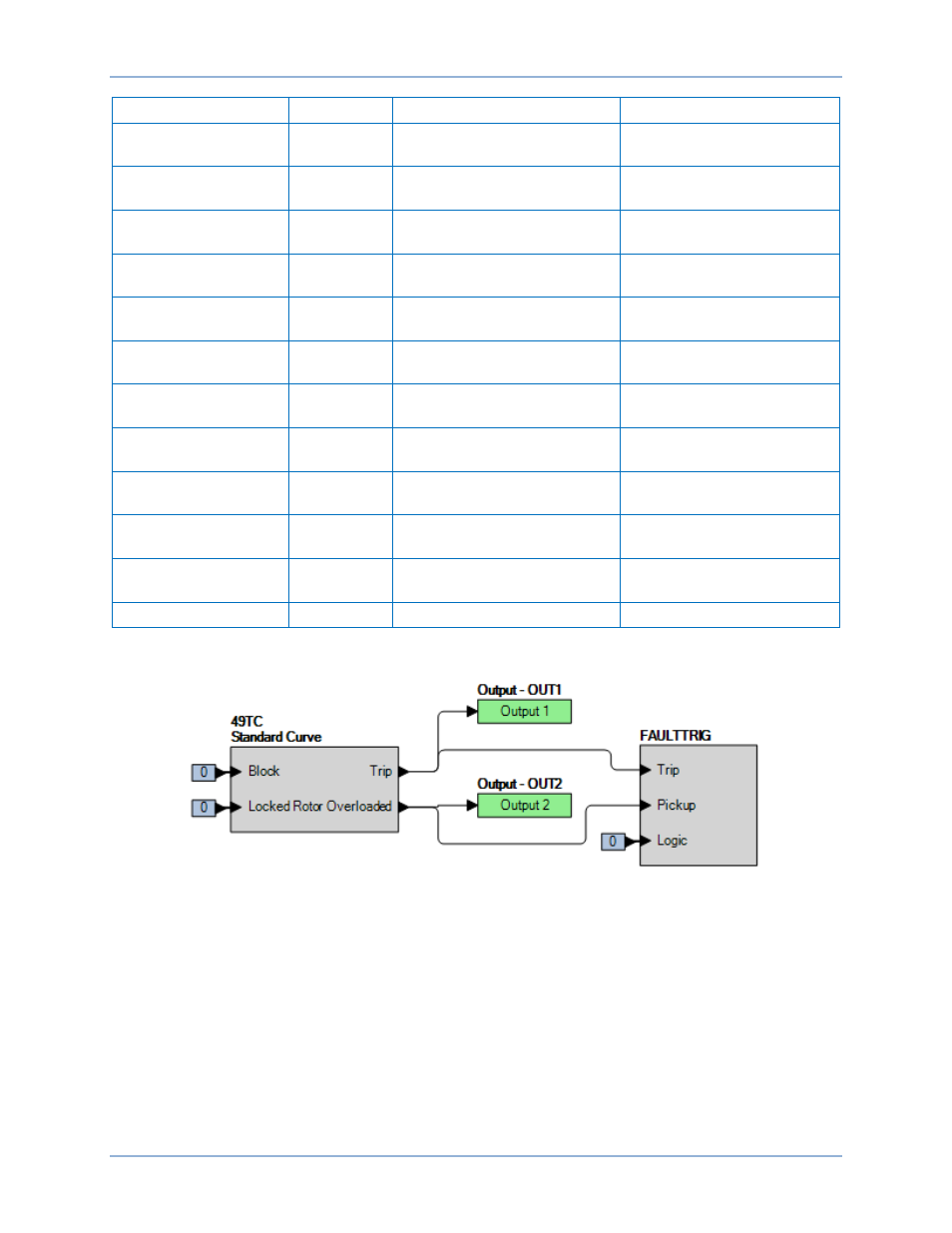
Step 2: Use BESTCOMSPlus to configure the BESTlogicPlus Programmable Logic shown in Figure
Figure 267. BESTlogicPlus Settings, Standard Curve
Step 3: Prepare to monitor the 49TC function operation. Operation can be verified by monitoring OUT1
(Tripped) and OUT2 (Overloaded). See Figure 267.
Step 4: Connect a three-phase 60 Hz current source to terminals D1 and D2 (IA), D3 and D4 (IB), and
D5 and D6 (IC).
Step 5: The following calculations are referenced in this test procedure.
The Overload Pickup Current is calculated in Equation 22.
𝐼
𝑡𝑝𝑢
= 𝑆 × 𝑆𝐹 × 𝐹𝐿𝐴 = 1 × 1 × 2 = 2 𝐴
Equation 22. Overload Pickup Current
Thermal Curve (49TC) Test
BE1-11m