Figure 2-1, Figure "location of critical temperature spots, Hardware preparation and installation – Artesyn ATCA-7365 Installation and Use (November 2014) User Manual
Page 53
Hardware Preparation and Installation
ATCA-7365 Installation and Use (6806800K65N)
53
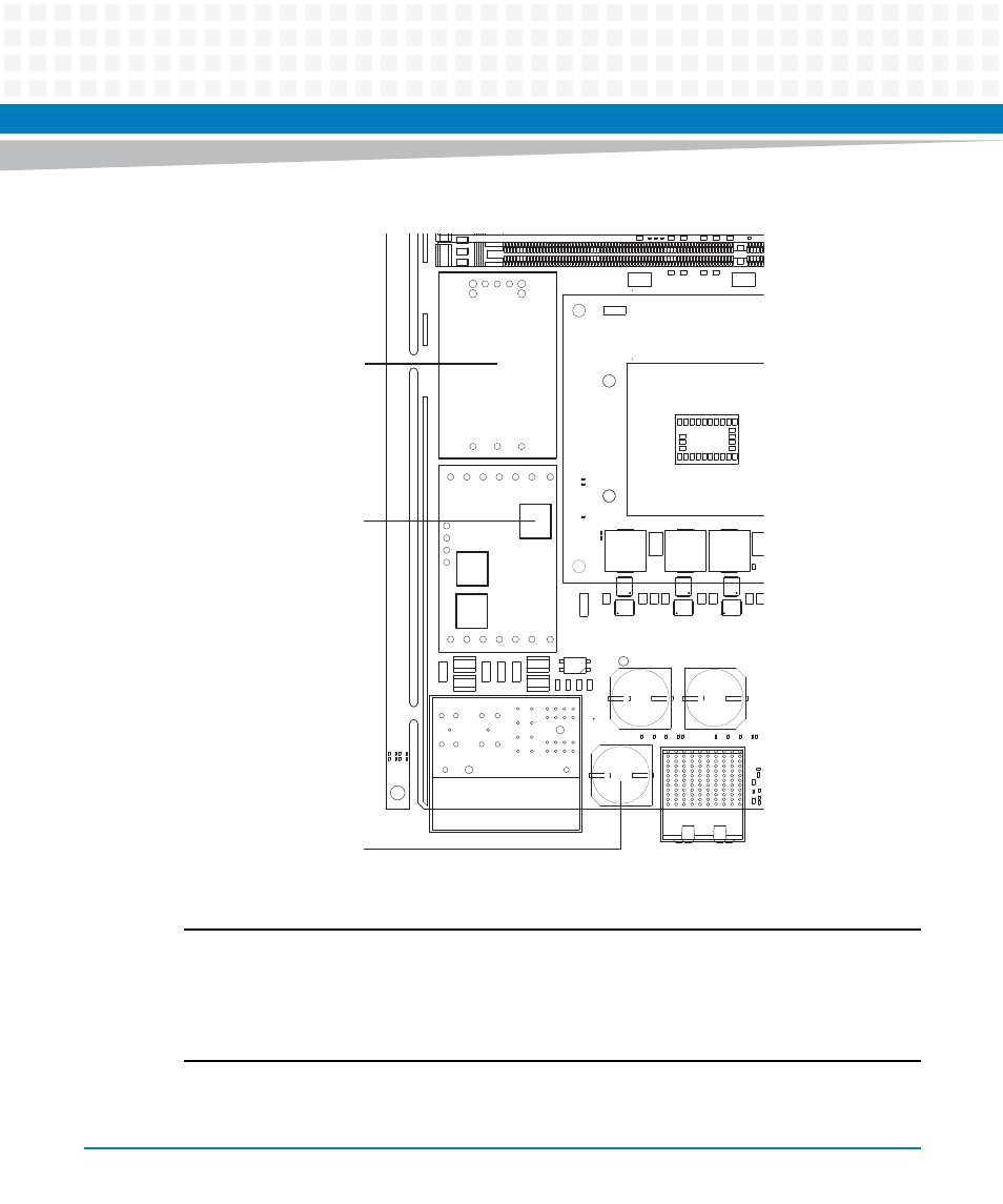
Note:
Temperature Test Point #1 (on DC/DC Converter Module): Max. 100°C (Exact location: In the
geometric middle of the heat spreader).
Temperature Test Point #2 (on Power Input Module): Max. 90°C (Exact location: On top of the
transformer).
Temperature Test Point #3 (on Hold-Up Capacitor): Max. 105°C
Figure 2-1
Location of Critical Temperature Spots (Blade Top Side)
C1272
C1258
C1260
C1274
C1275
C1276
F9905
F9907
C1262
C1263
R614
MH19
F9906
F9908
C963
R615
R616
R617
C4656
R1259
R1278
R1250
R1256
R1269
R1273
C962
R2858
R2859
R2860
R2861
R1249
R3123
R3045
P9910
J34
J35
J111
MHS3
CE29
CE30
Q51
MHS4
P23
CE31
Q77
Q50
R3627
R3628
R3629
R3630
R3635
R3636
R3651
R3652
F10
F7
F8
F11
MHS3
R1597
R1598
R1615
Q55
Q51
C3692
C3686
R3616
R3615
L83
C4053
MHS4
R2719
C4715
Q78
Q77
C3710
C3704
C3698
C3934
L93
C4529
C4530
C4531
C4532
C4533
C4534
J1
C4561
C4562
C4563
C4564
C4490
C4497
C4498
C4435
C4436
C4765
C4766
C4767
C3144
R2718
C4698
C4713
C4714
Q54
Q50
C3725
C3720
C3715
C3687
L82
C4527
C4528
C4566
8
5
5
4
C
7
6
5
4
C
C4559
C4494
C4495
C4496
C4433
C4434
C2029
C4768
C4215
C4699
C4700
+
A1
CD1
GH1
+
25
26
23
24
27
28
29
32
30
31 33
34
38
3
35
36
37
+
34
33
37
36
35
3
38
29
28
27
31
30 32
26
25
169
167
+
A10
CD10
GH10
5
6
10
11
7
8
9
12
13
14
17
18
19
15
16
20
21
22
+
21
20
24
23
22
14
13
12
16
15
19
18
17
6
5
9
8
7
11
10
+
+
3
1
2 4
AG
AR
AP
AN
AM
AL
AK
AJ
AH
BA
AY
AW
AV
AU
AT
M
L
K
J
H
G
Y
W
V
U
T
R
P
N
AF
AE
AD
AC
AB
AA
2
1
4
3
E
D
C
B
A
F
120
239
239
Temperature Test Point #1
Max. 100°C
Temperature Test Point #2
Max. 90°C
Temperature Test Point #3
Max. 105°C