2 telecom timer registers, Table 6-79, Telecom ch1_clk1b clock period msb register – Artesyn ATCA-7365 Installation and Use (November 2014) User Manual
Page 225: Table 6-80, Telecom ch1_clk1b clock period lsb register, Maps and registers

Maps and Registers
ATCA-7365 Installation and Use (6806800K65N)
225
The Clock period of CH1_CLK1B is measured periodically. The result of the measurement
(number of LPC clock cycles) is latched with a write access to the Telecom Backplane Clocking
Latch Register. The 16 bit value is stored in the register Telecom CH1_CLK1B clock period MSB
Register and Telecom CH1_CLK1B clock period LSB Register. When the clock is static or the
period is higher than a 16 bit value the result is always 0xFFFF.
6.4.22.2 Telecom Timer Registers
The Telecom Timer is decremented with each rising edge of the input clock.
The Telecom Timer is disabled when loaded with 0 (MSB and LSB Timer registers are 0). The
Telecom Timer can be programmed from 1 to 65535, which allows timeout values from 125
micro seconds to 8.191875 sec (based on an 8kHz input clock).
When a timeout occurs (the timer is 0) the timeout bit is set. See
Telecom
Status/Control Register. The Telecom Timer is reloaded with the timer start value stored in
Telecom Timer LSB Register and Telecom Timer MSB Register and armed again, waiting for a
rising edge of the input clock.
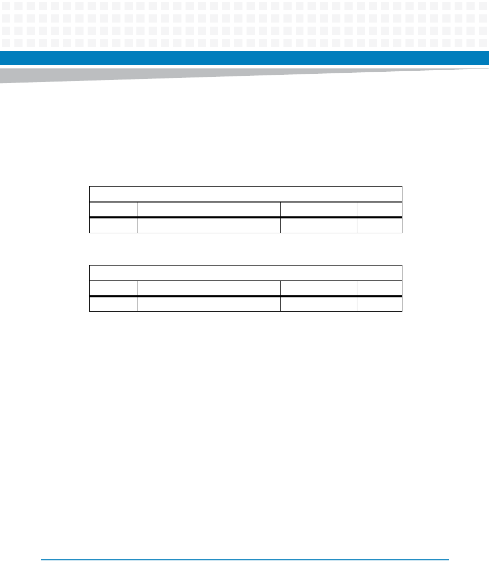
Table 6-79 Telecom CH1_CLK1B clock period MSB Register
Address Offset: 0x63
Bit
Description
Default
Access
7:0
MSB of CH1_CLK1B clock period
PWR_GOOD: 0xFF
LPC: r
Table 6-80 Telecom CH1_CLK1B clock period LSB Register
Address Offset: 0x62
Bit
Description
Default
Access
7:0
LSB of CH1_CLK1B clock period
PWR_GOOD: 0xFF
LPC: r
