AMETEK ReFlex Programming Manual User Manual
Page 73
DC Module Remote Programming
ReFlex Power™ Programming Manual
M380056-03 Rev L
69
Each power module’s trigger interface can be routed as a local signal used
only by the power module or can be connected to the buss trigger set by
SCPI command. When externally commanded, the ReFlex Power Controller
establishes this allocation and sends the power module the sequence of
trigger routing commands. The default is to have the power module’s triggers
signals all local to the module. The Module’s front panel trigger input and
output are separate and distinct; they are always available for internal usage.
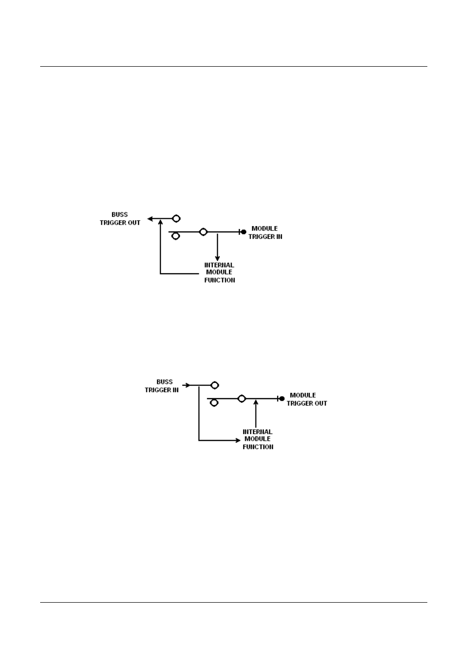
Figure 3-3 shows the signal routing from the trigger signal received by the
power module to the switch, (diagrammatic representation only). When the
switch is closed, opposite to that shown, then the received trigger is routed to
the backplane trigger buss.
Figure 3-3. Module/Buss Trigger Input
Figure 3-4 shows the signal routing for trigger transmitted from the power
module, which is out of power modules front panel connector. If the switch is
closed, opposite to the position shown, the backplane buss signal is also
routed to the modules front panel connector. Note in both cases, the module
can receive the trigger buss signal.
Figure 3-4. Module/Buss Trigger Out
Table 3-4 lists the SCPI commands associated with routing of the trigger
signals. Note this command assumes that buss trigger resources are
available, if they are not, the ReFlex Power™ Controller will respond with an
error message that the trigger cannot be allocated.