Common scpi commands – AMETEK ReFlex Programming Manual User Manual
Page 44
ReFlex Power™ Programming Manual
Controller Module Remote Programming
40
M380056-03 Rev M
2.9
COMMON SCPI COMMANDS
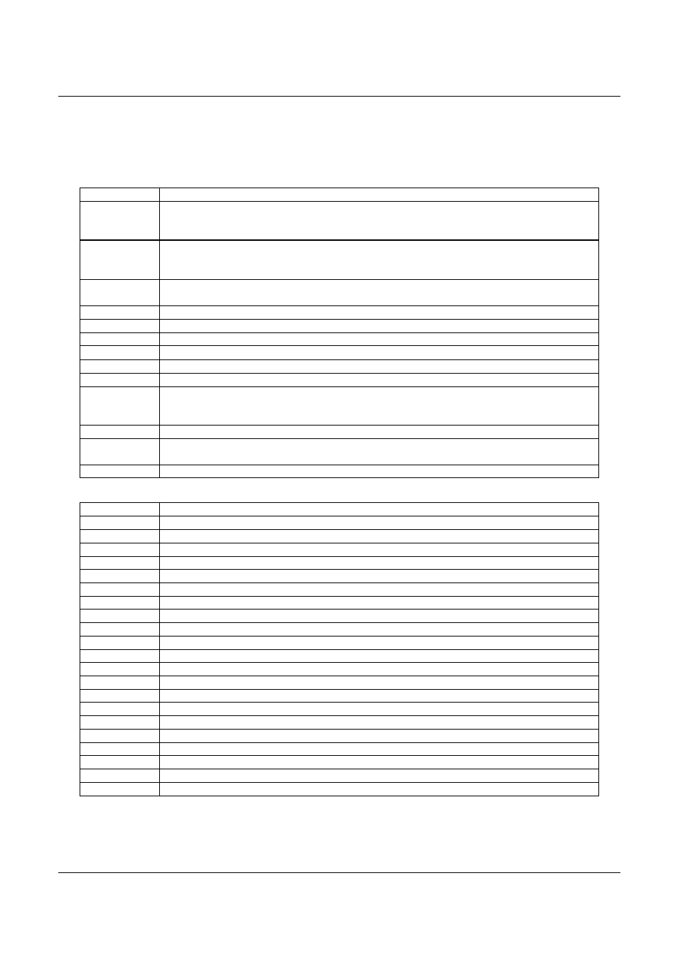
Table 2-5 shows commands that are common to all SCPI instruments.
Table 2-5. Common SCPI Commands
Command
Description
*CLS
Clears all status reporting data structures including the Status Byte, the Standard
Event Status Register, the Protection Event Status Register, and the Error Queue.
Enable registers are not cleared by this command.
*IDN
Returns the device identification as an ASCII string.
Response:
Example: ELGAR,RFP-C1LAN-000-0000,1234A56789,3.000.001
*OPC
Operation Complete Query: Returns value of 1, when all pending operations are
complete. Returns value of 0, when long, or multipart commands are not complete.
*STB?
Query User’s STatus Byte
*SRE?
Query the user’s enable bits in the Service Request Enable register
*SRE
Set the enable bits in the Service Request Enable register
*ESR?
Query the user’s standard Event Status Register, if bit 0 is set, a *RST is required.
*ESE?
Query the user’s Enable Standard Event status register
*ESE
Set the user’s enable bits in the Enable Standard Event status register.
*RST
Resets the specific slot module to its Power ON state. Clears status reporting data
structures, including the Protection Condition Status Registers. Enable registers are
not cleared by this command. *RST will reset all modules.
*TST
Initiate self test NOTE: Module must be OUTP:STATE 0 and not a group member.
*TST
Returns the results from the last self test the module performed. Returns a decimal
value, convert to Hex because more than one bit can be set. See Table 2-6.
*TST?
Returns the results from all the modules in the system or’ed together. See *TST
Table 2-6. Module *TST? Error Response Bits Note: The *TST command can’t be interrupted.
Response
Definition for all Modules
0x00
No Selftest Errors
0x01
The Firmware Version of the Controller and Module are not compatible
0x02
Flash image, tag mismatch
0x04
Flash image, version mismatch
0x08
Isolation relay closed
0x10
Sense relay closed
0x20
Current measurement error. For DC, measured current not zero.
0x40
Voltage measurement error
0x80
Output turn on error
0x100
RAM Configuration error
0x200
Module Enable is false, selftest can’t be executed
0x400
Module On, Active selftest can’t be executed
0x800
OVP test failed
0x1000
UVP test failed
0x2000
Housekeeping supply fault
0x4000
Overtemp fault
0x8000
Ground fault
0x10000
Tried to run selftest on a Group Member
0x20000
OCP test failed
0x40000
Configuration or Calibration file error
0x1000000
Failed at 0% Volt setting, only with other bits set