AMETEK ReFlex Programming Manual User Manual
Page 71
DC Module Remote Programming
ReFlex Power™ Programming Manual
M380056-03 Rev L
67
all modules via high-speed backplane signals. Each can be programmed to
control the module or have the module indicate its condition. This capability is
extendable to grouped modules as well.
In addition to or in conjunction with these synchronizing features, the ReFlex
Power™ module(s) can process a sequence (List) of pre-programmed
commands, frequently driven by trigger signals, to control its output.
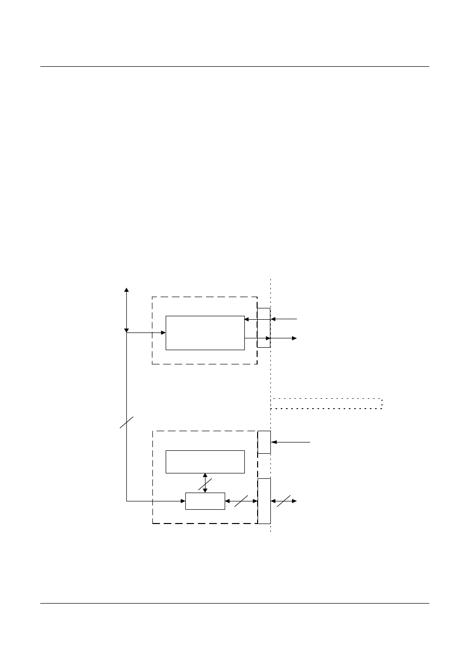
Figure 3-1 diagrams the various trigger ports and trigger architecture in the
ReFlex Power™ system. Each module has a unique set of trigger in/out
ports. These are termed the module ports and have the same address as the
power module. There are up to four bussed trigger ports that are shared by
all modules. Each power module and the ReFlex Power™ Controller can
access these signals to either send or to receive trigger signals. The limitation
on the number of these signals is due to their also being used to support DC
series groups and to create fault groups. Hence the sum of DC series groups,
fault groups and allocated buss trigger signals must be less than or equal to
four.
R F P C O N T R O L LE R
T R IG G E R LO G IC
4
4
4
M O D U LE T R IG G E R IN P U T
< F A >
M O D U LE T R IG G E R O U TP U T
< F A >
T R IG G E R B U S S
S H A R E D W IT H
A L L M O D U LE S
M O D U LE
T R IG G E R
LO G IC
R F P IN TE R N A L
B A C K P LA N E
< A , B , C , D >
M O D U L E
R F P C O N TR O L L E R
R O U T IN G
T R IG G E R
I/O
< F A , FB , F C , F D >
4
S O F T W A R E TR IG G E R
L
A
N
U S E R S P A C E
Figure 3-1. RFP Trigger Logic