AMETEK ReFlex Programming Manual User Manual
Page 25
Controller Module Remote Programming
ReFlex Power™ Programming Manual
M380056-03 Rev L
21
o
For all other modules (power supplies and loads), you will
need either Loop-back Connector Assembly 5380508-01 or
Cable Assembly 5380443-01 or-03.
2.4.2
E
THERNET
S
ETUP
P
ROCEDURE
The ReFlex Power™ Quick Reference Guide (M380056-04) is a
condensed version of this procedure for Ethernet setup.
1.
With all power disabled, assemble your ReFlex Power™ system and
main power connections according to the ReFlex Power™ Operation
Manual, M380056-01.
2. Disable the Remote Inhibit of the Controller module, by connecting their
discrete signals with a jumper plug that connects Pins 1 and 9 on the
front panel interface connector, using either Loop-back Connector
Assembly 5380509-01 or Cable Assembly 5380441-01 or –03.
3. Enable the voltage output of all other power supply and/or load
modules by connecting their discrete signals with a jumper plug that
connects Pins 1 and 6 on the front panel interface connector of each
module, using either Loop-back Connector Assembly 5380508-01 or
Cable Assembly 5380443-01 or-03.
4. Create either a Network or direct connection between the control
computer and the ReFlex Power™ system, using Category 5 or 5e (Cat
5) cables with RJ45-type connectors, as follows:
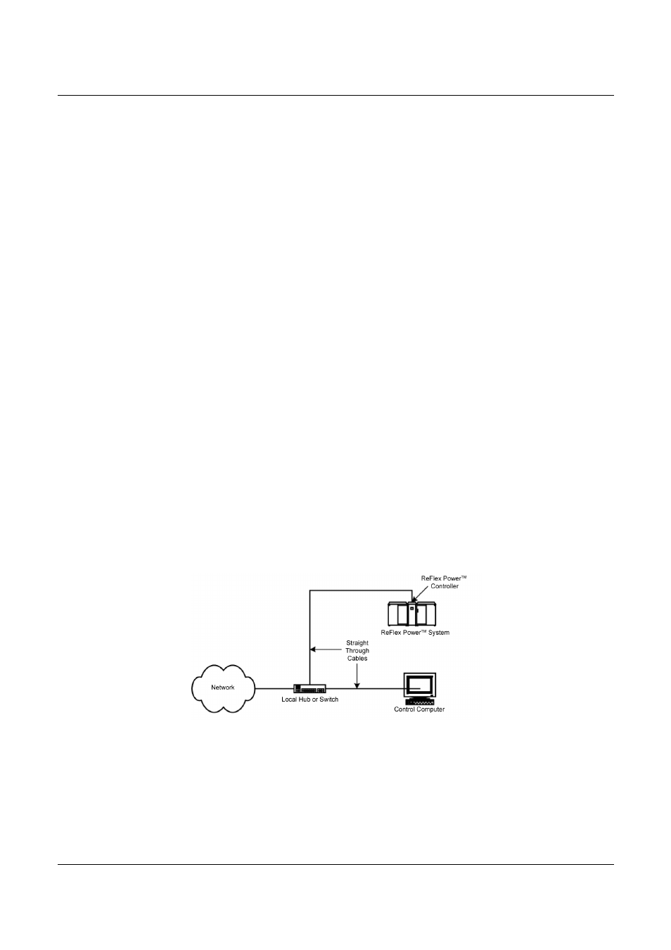
Ethernet Network Connection
A Network connection via local router, or switch isolates the local
nodes and segments from the rest of the Network, a hub does not. Use
two straight through cables to connect the control computer and the
ReFlex Power™ Controller from their respective Net/LAN connectors,
to a local router, switch or hub (Figure 2-1). ReFlex Power™ Controller
will DHCP if available from the network.
Figure 2-1. Ethernet Network Connection