Connecting the nodebuilder fx/pl hardware – Echelon NodeBuilder FX User Manual
Page 43
NodeBuilder FX User's Guide
29
Connecting the NodeBuilder FX/PL Hardware
To connect the NodeBuilder FX/PL hardware, follow these steps:
1. Unpack the equipment from the shipping carton. Avoid touching areas of integrated circuitry, as
static discharge could damage circuits.
2. Verify that all of the following hardware and software items are present.
Item Qty
LTM-10A Platform (with built-in PL-22 power line transceiver)
1
LTM-10A Power Supply
1
Gizmo 4 I/O Board
1
L
ON
W
ORKS
Power Line Couplers. One line-to-neutral (L-N) coupler, and
one line-to-earth (L-E) coupler.
2
U20 USB Network Interface
1
U20 USB Network Interface Power Supply
1
USB Extension Cable
1
PLM-22 Accessory Kit
1
NodeBuilder FX CD
1
LonMaker CD
1
LonScanner CD
1
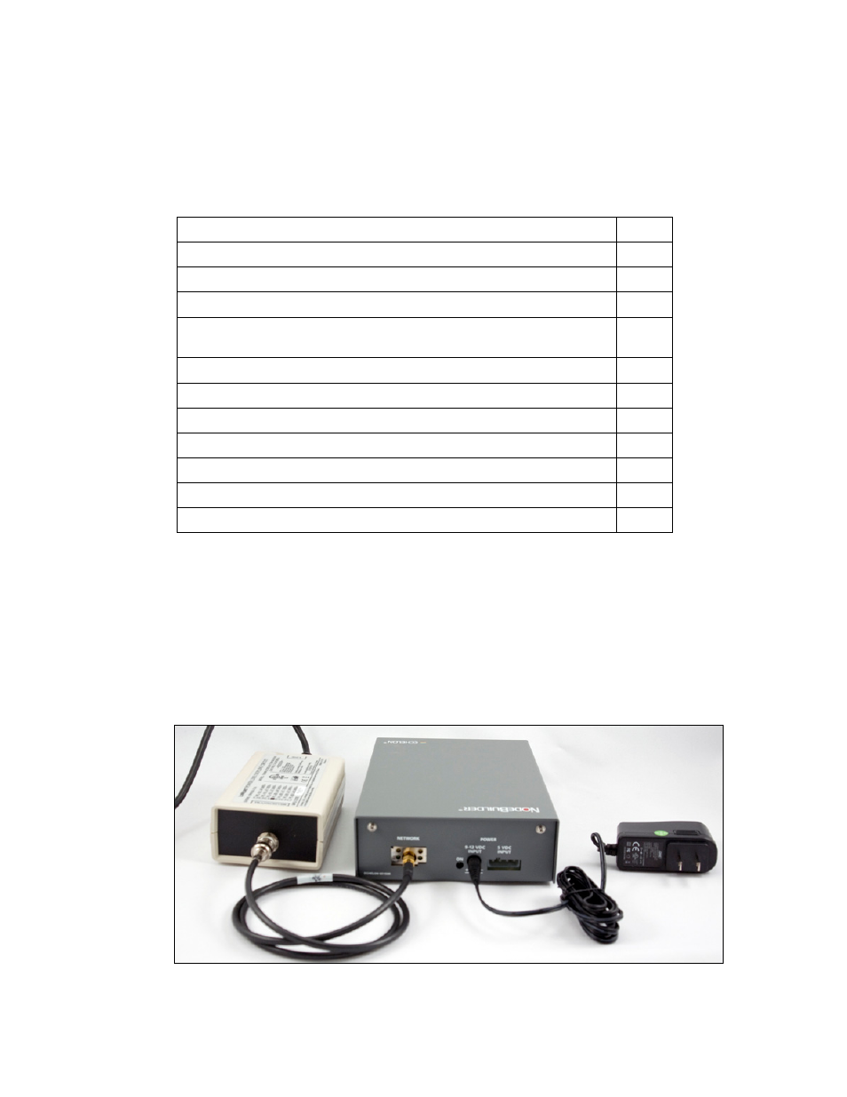
3. Connect either the line-to-neutral (L-N) or line-to-earth (L-E) L
ON
W
ORKS
Power Line Coupler
included with the NodeBuilder FX/PL tool to the Network input on the LTM-10A Platform,
connect a power cable (not included) to the coupler, and then plug the power cable into a power
outlet.
If you use the L-N coupler, you can directly use the included USB 20 network interface and power
supply/coupler to connect your computer running the NodeBuilder tool to a PL-20 channel as
described in step
6. If you use the L-E coupler, you must supply your own power supply/coupler
for the USB 20 network interface.
4. Connect the LTM-10A power supply to the 9–12VDC INPUT on the LTM-10A Platform, and
then insert the power supply into a power outlet.