2 dimensions (cont'd), Cabinet d door hinges / handles, Figure 4 - d cabinet door hinges – Reznor RECC Unit Installation Manual User Manual
Page 8: Return air opening (vertical only) is optional
Form I-MAPSIII&IV, Page 8
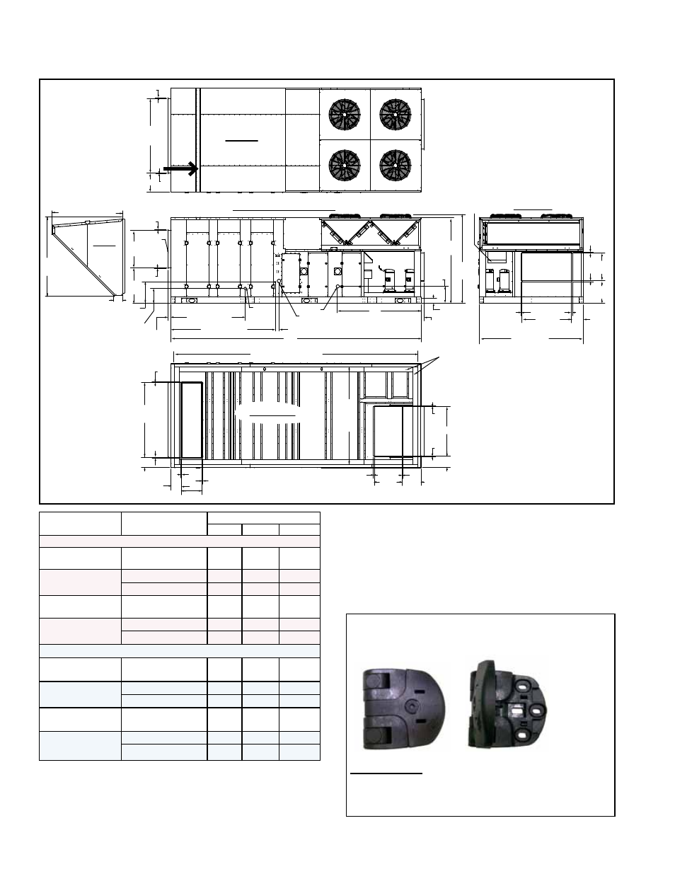
Model RDCB & RDDB NOTES:
•
Heat Sizes 500, 600, 700, 800 have one heat module.
•
Heat Sizes 1000, 1200, 1400, 1600 have two heat modules
(illustrated).
Model and Cooling
Size
with Gas Heat
Section Size
CODES (FIGURE 3B)
A
B
C
Dimensions - inches (±1/16)
RCB, RECB 360, 480,
600, 720
N/A
208-3/8
--
201-15/16
RDCB 360, 480, 600,
720
500, 600, 700, 800
208-3/8 80-3/16 201-15/16
1000, 1200, 1400, 1600 240-3/4 80-13/16 234-5/16
RDB, REDB 418, 444,
602, 722, 842
N/A
208-3/8
--
201-15/16
RDDB 418, 444, 602,
722, 842
500, 600, 700, 800
208-3/8 80-3/16 201-15/16
1000, 1200, 1400, 1600 240-3/4 80-13/16 234-5/16
Dimensions - mm (±2)
RCB, RECB 360, 480,
600, 720
N/A
5293
--
5129
RDCB 360, 480, 600,
720
500, 600, 700, 800
5293
2037
5129
1000, 1200, 1400, 1600
6115
2053
5952
RDB, REDB 418, 444,
602, 722, 842
N/A
5293
--
5129
RDDB 418, 444, 602,
722, 842
500, 600, 700, 800
5293
2037
5129
1000, 1200, 1400, 1600
6115
2053
5952
FIGURE 3B - General
Arrangement
and Dimensions -
inches (mm) of
D Cabinet Models
NOTES:
•
Gas heat section
information applies only
to Models RDCB and
RDDB.
•
Discharge is either
horizontal or vertical (not
both).
•
Return air opening
(vertical only) is optional.
4.2 Dimensions (cont'd)
4.2.2 Dimensions of Cabinet D Size Models and Cabinet D Door Hinges
Cabinet D Door Hinges / Handles
The filter, coil, and fan/motor cabinet doors can be
opened from the left or right. On the side of the door
to be opened, unlock the two hinges with an allen key.
Pull out unlocked "fronts" of the hinges to 90 degrees to
expose handles needed to open the door.
Re-lock hinges when doors are closed.
Door Hinges - Use an allen key to unlock
hinges to open D Cabinet doors from left or
right.
Locked
Unlocked
3/4 (19)
3/4 (19)
3/4 (19)
3/4
(19)
71-7/8
(1826)
18-3/16 (462)
Outside
Air
Inlet
36
(914)
34-1/4
(870)
20-5/8
(524)
14-1/2
(368)
3-1/16
(78)
Filter Access
Coil Access
Fan & Motor
Access
71-5/8 (1819)
Coil
Drain
100-5/8 (2556)
Gas
Electric
(24V left; supply right)
3-3/8 (86)
A
C - Inside of Base
B
3-1/16
(78)
4-7/8 (124)
Bottom
of Base
to Curb
Mounting
Surface
16-1/2
(419)
82-5/16
(2091)
85-9/16
(2173)
Control Access
Heat Access
Heat Access
Combustion
Air Hood
3/4 (19)
3/4 (19)
3/4
(19)
3/4 (19)
47-11/16
(1211)
100-1/4 (2546)
26-3/4
(679)
21-5/8
(549)
11-1/4
(286)
Top View
Front View
Left Side View (Control Side)
Return Air
Duct
Connection
3/4
(19)
3/4
(19)
3/4
(19)
3/4
(19)
72
(1829)
10 (254)
10-3/16
(259)
19-7/8 (505)
93-3/4
(2381)
Inside
of
Base
3/4 (19)
3/4
(19)
3/4
(19)
3/4
(19)
26-3/4
(679)
47-11/16 (1211)
11-1/4 (286)
Vertical
Discharge Duct
Connection
Roof Curb Mounting Surface
Bottom View
18-1/4 (464)
Horizontal
Discharge
Duct Connection
Condenser Section
Compressors
48-11/32” (1228mm)
54-1/4”
(1378mm)
6-1/4” (159mm)
Side View
Hood
(Option AS16)
FIGURE 4 - D Cabinet Door Hinges
- REDB Unit Installation Manual RECB Unit Installation Manual RDDC Unit Installation Manual RDCC Unit Installation Manual RDDB Unit Installation Manual RDCB Unit Installation Manual RDC Unit Installation Manual RCC Unit Installation Manual RDB Unit Installation Manual RCB Unit Installation Manual REDC Unit Installation Manual MAPSIV Unit Installation Manual MAPSIII Unit Installation Manual