0 mechanical, 1 energy recovery module (option er1), 0 mounting (cont'd) – Reznor RECC Unit Installation Manual User Manual
Page 30: 5 rigging and lifting the maps, Units (cont'd)
Form I-MAPSIII&IV, Page 30
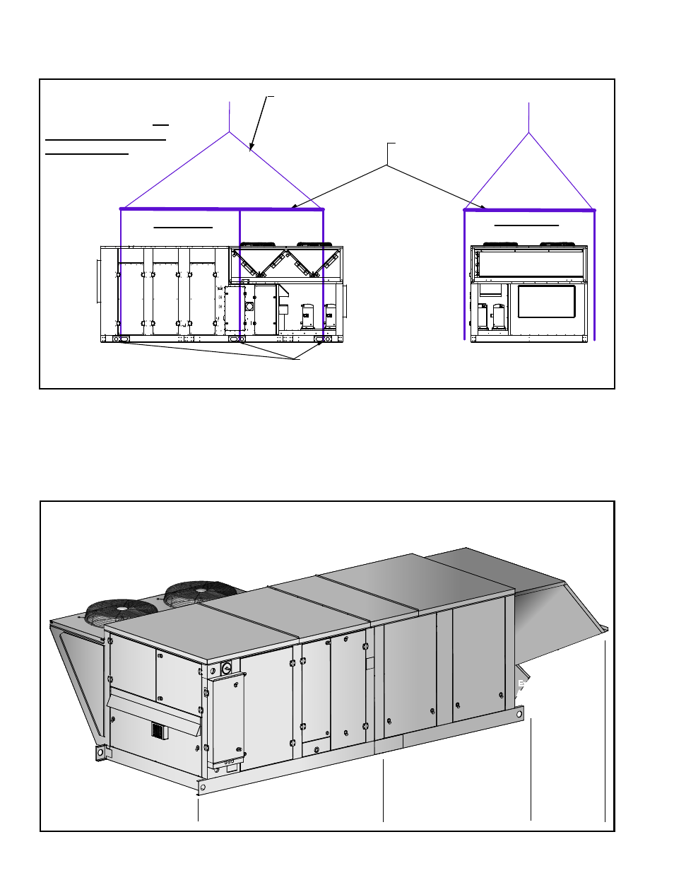
Spreader bars
are REQUIRED.
Six Lifting Holes - ALL lifting points MUST be used.
Lift straight up with vertical force only.
Side View
MAPS III D Cabinet
Front View
MAPS III D Cabinet
After test lift, adjust length as needed
so that the unit will remain horizontal
throughout the lift.
FIGURE 14B - Rigging
and Lifting a MAPS
®
"D" Cabinet using all
six lifting points and
spreader bars
6.0 Mechanical
6.1 Energy Recovery Module (Option ER1) - A, B, and C
If ordered with an energy recovery module, the module is shipped separately and
must be lifted separately and mated to the inlet side of the already mounted MAPS
®
unit.
Follow the lifting and mating instructions in the manual supplied with the
energy recovery module (Form I-MAPS III&IV-ER).
NOTE: Control information is in Form CP-MAPS-D15/16 that was shipped with this
manual.
Compressor
Cabinet
Power
Cabinet
Gas Heating
Section
Control Cabinet
Fan
Section
DX Cooling
Coil
Mixed
Air
Section
Energy
Recovery
Wheel
Section
Filtered
Outdoor Air
Hood
Condenser
Section
Exhaust
Air Hood
Exhaust
Air Hood
MAPS® Unit
Cabinet Size A, B, or C
Energy Recovery Module
Option ER1 - shipped factory-
assembled (including exhaust
hood) to be mated to the
MAPS unit at the installation
site
Outside Air
Hood, Option
AS19 -
shipped for
assembly and
installation at
the job site
after module
is mated to
the unit
FIGURE 15 - MAPS
®
Unit with Energy Recovery
Module and Outside Air Hood Installed
5.5 Rigging and Lifting the MAPS
®
Units (cont'd)
5.0 Mounting (cont'd)
- REDB Unit Installation Manual RECB Unit Installation Manual RDDC Unit Installation Manual RDCC Unit Installation Manual RDDB Unit Installation Manual RDCB Unit Installation Manual RDC Unit Installation Manual RCC Unit Installation Manual RDB Unit Installation Manual RCB Unit Installation Manual REDC Unit Installation Manual MAPSIV Unit Installation Manual MAPSIII Unit Installation Manual