2 supply fan (blower) start/stop control, 2 supply fan (blower) start/ stop control – Reznor RECC Unit Installation Manual User Manual
Page 49
Form I-MAPSIII&IV, P/N 222917R9, Page 49
CAUTION: The same ground reference has to be used for the CO
2
sensor and for the control
system.
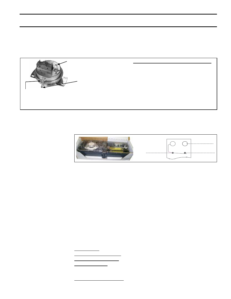
Option BE18, Dirty
Filter Switch
All "C" Cabinet systems have either 2" or 4" pleated disposable or permanent filters. D
Cabinet systems have 4" pleated disposable or permanent filters. If dirty filter indicator
Option BE18 was ordered, a dirty filter switch is in the electrical compartment with tub-
ing sensors placed on either side of the filters as shown in
FIGURE 25.
The pressure switch is in the low voltage electrical compartment. Follow the instruc-
tions in
FIGURE 28F to set the dirty filter switch.
FIGURE 28F -
Dirty Filter Switch,
P/N 105507
Setscrew (on front of switch)
must be manually adjusted after
the system is in operation.
Negative pressure
connection is toward the
"front or top" of the switch
(senses blower side of filters)
Positive pressure
connection is toward the
"back or bottom" of the
switch (senses air inlet
side of filters)
Instructions for Setting Dirty Filter Switch -
With clean filters in place; all doors closed (except
electrical compartment); and the blower operat-
ing, increase the pressure setting by adjusting
the setscrew on the switch clockwise until the
filter light is energized or the screw is bottomed
out. At that point, adjust the setscrew three full
turns counterclockwise or until the screw is top-
ended. At that setpoint, the filter light will be acti-
vated at approximately 50% filter blockage.
Option BE17,
Photoelectric Duct
Smoke Detector
FIGURE 28G - Wiring
Connections for Option
BE17 Photoelectric
Duct Smoke Detector
24V
9
C
10
NC
SMOKE DETECTOR
6
16
The photoelectric smoke detector (
P/N 159553) used in Option BE17 is field mounted
on the ductwork. A field-supplied duct air sampling tube is required. Follow the manu-
facturer's installation instructions. Comply with the requirements in Paragraph 8.1.1
when running the sensor wire. Wires will connect to the controller expansion board.
Refer to the unit wiring diagram.
8.2 Supply Fan
(blower) Start/
Stop Control
The I/Q control can be programmed to operate the unit in two modes: Occupied and
Unoccupied
The supply fan (blower) starts/stops automatically through a local time of day schedule
or remote contact closure commanding the system to occupied mode. If the controller
is connected to a building automation system, other external controllers can control the
mode of operation.
Upon a command for occupied mode, the supply fan starts and runs continuously.
There is a differential pressure (air proving) switch that indicates proof of fan operation.
The supply fan is subject to safety devices, such as duct high limit switches, fire alarm
relays, smoke detectors, low temperature limits, fan status and others devices which
can turn the supply fan OFF.
The control could be programmed with an optional optimum start sequence, which
allows the supply fan to operate and bring the space temperature to its setpoint value
just before the unit is scheduled to be in occupied mode.
If the unit is in the unoccupied mode, the supply fan is turned OFF and will only run
intermittently to maintain night setback/setup space conditions. During the unoccupied
mode, if the override push button on the user wall interface is pressed, the unit will
switch to occupied mode for 60 minutes.
Control Mode (Default = Stand alone): Stand alone or BAS
Push Button Override Timer (Default=60 minutes): Range=15 minutes to 240 minutes
Hardwire Occupancy Input (Default = Disabled): Enabled or Disabled
Optimum Start/Stop (Default=Enabled): Enabled or Disabled
NOTE: The hardwired occupancy input will override the local or remote schedule. If
this point is active, the software schedules do not function.
Optional Supply Fan Controls: Optional variable frequency drive (Option VFD) can be
controlled by a number of optional sensors.
Adjustable Control
Parameters from Local
Display (in the control
compartment) and
Remote Display (if
equipped)
- REDB Unit Installation Manual RECB Unit Installation Manual RDDC Unit Installation Manual RDCC Unit Installation Manual RDDB Unit Installation Manual RDCB Unit Installation Manual RDC Unit Installation Manual RCC Unit Installation Manual RDB Unit Installation Manual RCB Unit Installation Manual REDC Unit Installation Manual MAPSIV Unit Installation Manual MAPSIII Unit Installation Manual