Gas capacity controls – Reznor RECC Unit Installation Manual User Manual
Page 57
Form I-MAPSIII&IV, P/N 222917R9, Page 57
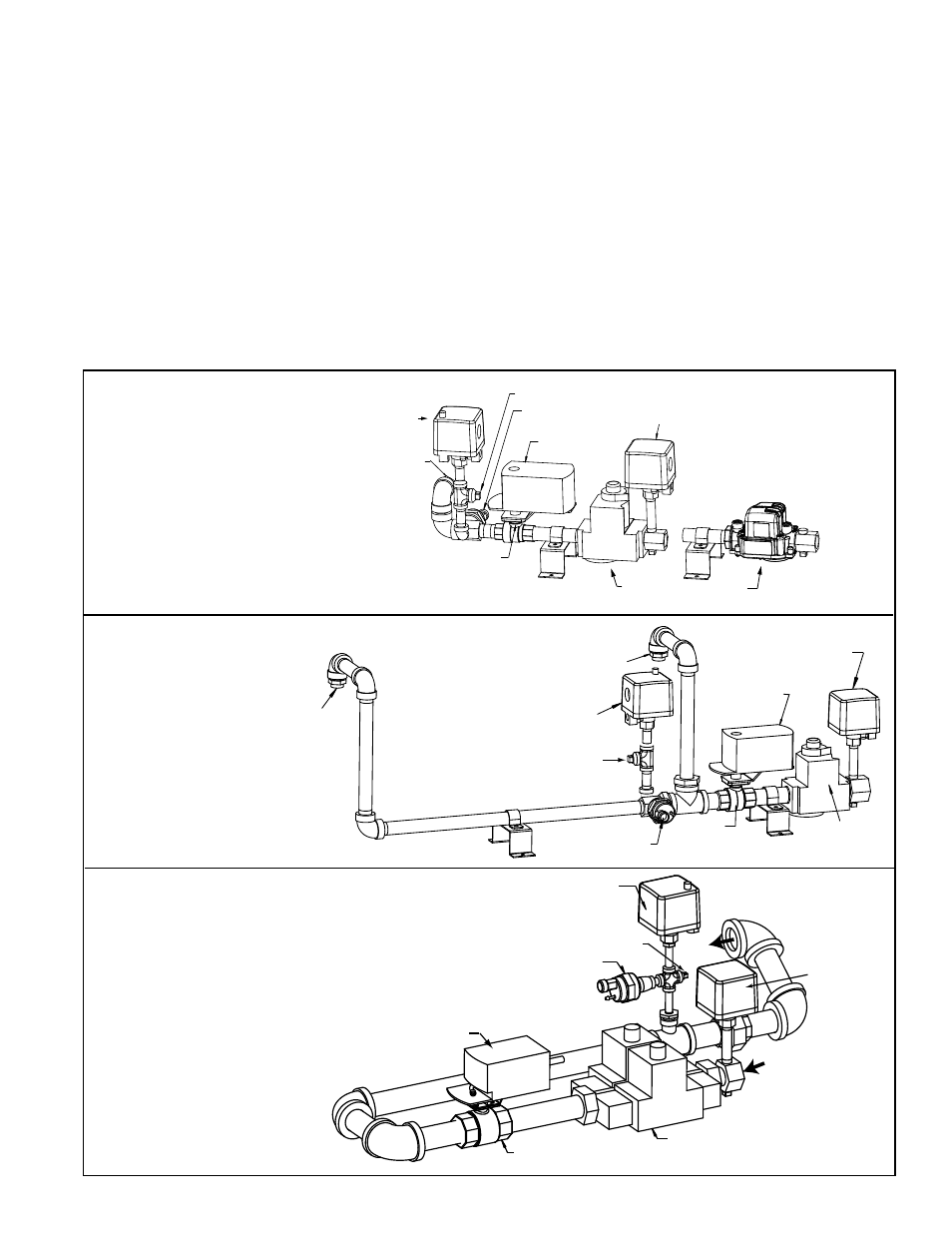
Gas Capacity Controls
The modulating control system (Option AG70) on single heat section Sizes 100 through
700 is approximately 8:1 turndown and 16:1 turndown on dual heat section Sizes 800,
1200, 1400 and 1600. All deep modulating, single furnace gas trains include a safety
shutoff, single-stage or dual single-stage valve, and a modulating ball valve. All two-
furnace gas trains (D Cabinet only) include a safety shutoff, dual single-stage valve
and a modulating ball valve on one furnace and a safety shutoff, dual single-stage
valve on the other furnace. See Cabinet A gas train in
FIGURE 38A, Cabinet B in FIG-
URE 38B, Cabinet C in FIGURE 38C, and D Cabinet gas train in FIGURE 39. FIGURE
40 illustrates the ball valve and actuator used in all manifolds.
A call for heat is determined by the cooling/heating main controller (See Paragraph 8)
based on heating air setpoint and inlet air temperature.
If natural gas supply pressure is too high, install a regulator in the supply line before it
reaches the heater. The regulator should not allow greater than 1/2 psig (14" w.c.) to
the factory installed valves, even in the off cycle.
If natural gas supply pressure is too low, contact your gas supplier.
Orifice
Adapter
Ball Valve
Optional High Gas
Pressure Switch
Transducer
Ball Valve
Actuator
Gas Valve (either style)
Optional Low Gas
Pressure Switch
Manifold
Pressure Tap
FIGURE 38A - Gas
Train in A Cabinet
Gas Heat Section
Sizes 100, 150, 200
Optional High Gas
Pressure Switch
Optional
Low Gas
Pressure
Switch
Dual, Single-Stage
Gas Valve
Ball Valve
Transducer
From Gas
Supply
To
Burner
Manifold Pressure Tap
Ball Valve
Actuator
FIGURE 38C - Gas Train in
C Cabinet Gas Heat Section
Sizes 400, 500, 600, and 700
Orifice
Adapter
Orifice Adapter
Optional High Gas
Pressure Switch
Transducer
Ball
Valve
Single-Stage
Gas Valve
Ball Valve
Actuator
Optional Low Gas
Pressure Switch
Manifold Pressure Tap
FIGURE 38B -
Gas Train in B
Cabinet Gas Heat
Section Sizes 250
and 300
- REDB Unit Installation Manual RECB Unit Installation Manual RDDC Unit Installation Manual RDCC Unit Installation Manual RDDB Unit Installation Manual RDCB Unit Installation Manual RDC Unit Installation Manual RCC Unit Installation Manual RDB Unit Installation Manual RCB Unit Installation Manual REDC Unit Installation Manual MAPSIV Unit Installation Manual MAPSIII Unit Installation Manual