0 mounting (cont'd), Unit with energy recovery module, Roof curb weight – Reznor RECC Unit Installation Manual User Manual
Page 22
Form I-MAPSIII&IV, Page 22
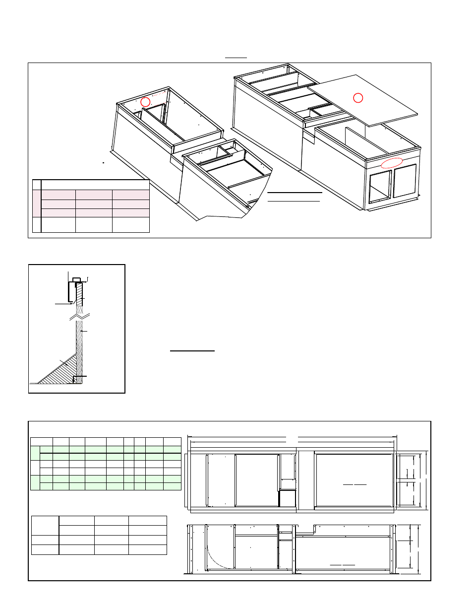
FIGURE 10F - Install
the Curb End with
Duct Connections
(
3
Y'S
) and the
Energy Recovery
Section Duct Top
(
Z
)
Counter
Flashing
(by installer;
install after
curb assembly)
Insulation
2 x 4 Wood
Nailer
Cabinet
Cant Strip
(by installer)
Weld, bolt,
or lag screw
curb to deck
structure.
FIGURE 10G -
Curb Detail
FIGURE 10H - Dimensions (inches/mm)
Weights and Dimensions of Options CJ54 & CJ53 for MAPS
®
unit with Energy Recovery Module
Cabinet
R
S
T
U
V W
X
Y
A*
inches
15
2-5/16 34-13/16 38-5/8 18 32
133 136-3/4
mm
381
59
884
981 457 813 3378
3473
B*
inches
22-1/2 2-5/16 49-13/16 53-5/8 18 32
133 136-3/4
mm
572
59
1265
1362 457 813 3378
3473
C*
inches
28-1/4 2-5/8 61-5/16 65-1/8 22 36 167-7/8 171-5/8
mm
718
67
1557
1654 559 914 4264
4359
*See Model Size / Cabinet Size Cross
Reference, pages 71-72.
Cabinet
Size *
A
B
C
Opt CJ54 Opt CJ4 Opt CJ53
lbs
675
785
1087
kg
306
356
493
Roof Curb Weight
9. Complete field installation of the roof curb
a) Check the assembly for squareness. The curb must be adjusted so that the
diagonal measurements are equal within a tolerance of ±1/8” (±3mm).
b) Level the roof curb. To ensure a good weatherproof seal between the unit curb
cap and the roof curb, the roof curb must be leveled in both directions with no
twist end to end. Shim as required and secure curb to roof deck.
c) Install field-supplied flashing (FIGURE 10G).
d) Apply 1/4" x 1-1/4" foam sealant tape to both the top surface of the curb rails
and the top surface of the perimeter of the duct dividers, being sure to make
good butt joints at all corners.
10. Lift the MAPS
®
unit on to the prepared curb (See Rigging and Lifting, Paragraph
5.5).
IMPORTANT: Verify that the unit will be placed in the correct airflow
orientation to mate properly with the discharge and return air openings.
Remember that the energy recovery module is at the discharge end of the curb.
11. After the MAPS
®
unit is in place, follow the instructions shipped with the energy
recovery module (Form I-MAPSIII&IV-ER) to lift and mate the energy recovery
module to the MAPS
®
unit.
5.0 Mounting
(cont'd)
5.4.2.2 Roof Curbs for Horizontal Airflow (Options CJ54 & CJ53) for
Cabinets A, B, and C WITH an Energy Recovery Module (cont'd)
5.4.2 Roof Curbs for Horizontal Airflow - Cabinets A, B, C (cont'd)
Y
Z
(Return
Air
Cap)
A
B
B
C
G1
G2
M
B
G2
M
N
G1
R
U
U
W
S
S
R
X
3/4” Hex Head Cap Screws with
Lockwashers and Hex Nuts (8 per corner)
2” Lag Screw and
Lockwasher (2 per corner)
Corner Hardware
for attaching “Y”:
F
(Insulation up)
3 Y’s
Supply
Duct
Supply
Duct
X
Y
Roof Curb Option CJ53 & CJ54
for MAPS with Option ER1
Energy Recovery Module
TOP VIEW
Roof Curb Option CJ53 & CJ54
for MAPS with Option ER1
Energy Recovery Module
SIDE VIEW
Return Air Duct
R
S
T
U
R
V
W
10-3/16
(259)
NOTE: Top duct liner is one piece
(illustrated) on Cabinet A. Cabinets B
and C have a two-piece top duct liner.
(MAPS Unit)
(Energy Recovery Unit)
NOTE: Cabinet Sizes B
and C - Insulated Duct
Top (Code Z) is two piece
ID
P/N by Cabinet Size
Y
A-261656 B-261657
C-261672
A-261386 B-261387
C-261414
A-261388 B-261389
C-261415
Z A-262545 B-262552
&262556
C-261676
&262435
- REDB Unit Installation Manual RECB Unit Installation Manual RDDC Unit Installation Manual RDCC Unit Installation Manual RDDB Unit Installation Manual RDCB Unit Installation Manual RDC Unit Installation Manual RCC Unit Installation Manual RDB Unit Installation Manual RCB Unit Installation Manual REDC Unit Installation Manual MAPSIV Unit Installation Manual MAPSIII Unit Installation Manual