0 optional equipment (cont'd) – Reznor RECC Unit Installation Manual User Manual
Page 60
Form I-MAPSIII&IV, Page 60
High Altitude Operation for Modulating Gas Control Option AG70
Option AG70 modulating gas control system does not require a gas pressure adjust-
ment derate at high altitude. The patented control system works on a principle of
safe, continuous gas and combustion air monitoring and adjustment. As the mass
flow through the combustion system changes, due to the lower oxygen level at high
altitude, the control system senses the change, automatically reducing the firing rate
of the burner.
High Altitude Operation
Gas Pressure Safety
Switches, Option BP4
See location of optional gas pressure safety switches in
FIGURE 38 A, B, C or 39. The
optional gas pressure switches are safety controls designed to protect the manifold
and burner from extreme upstream gas piping system failures that would cause an
increase or decrease in the regulated gas pressure.
The low gas pressure switch is an automatic reset which is set to activate if the gas
pressure is 50% of the minimum as stated on the rating plate.
The high gas pressure switch is a manually reset switch that is set to activate if the gas
pressure is 125% of the manifold pressure stated on the rating plate.
9.2 Gas Heat - Models RDCB, RDDB, RDCC, RDDC (cont'd)
9.0 Optional
Equipment
(cont'd)
9.2.1.2 Gas Piping and Pressures (cont'd)
9.2.1 Gas Heat Module - Mechanical (cont'd)
9.2.2 Gas Heat
Module Ignition and
Deep Modulation
Systems
MAPS
®
unit with a gas heat section are equipped with a proprietary integrated combus-
tion control system. This system controls the direct spark ignition, safety and modulat-
ing valves, and modulates the speed of the venter motor to assist in obtaining the 8:1
or 16:1 firing rate turndown.
Note that during normal operation of this deep modulation control system, the current
draw of the venter motor can exceed the full load amp rating on its nameplate. This
condition is common when employing electronic wave-chopping technology to reduce
the running speed of a single-phase type PSC alternating current motor. The increased
current is a result of increased slip, which is the difference between the rotation speeds
of the rotor and stator fields. All motors used in MAPS
®
systems are custom designed
and built for this unique modulating application and cannot be replaced with a non-
approved motor.
The ignition module requires an analog input voltage greater than 2VDC for ignition
startup and above 9.5VDC to achieve high fire.
The function of the ignition system is basically the same in all MAPS
®
systems, but
the components and features vary in the D Cabinet. The normal heat cycle operating
sequence of the A, B, & C cabinets and the D cabinet are identified in the following
paragraphs. For more detailed information, see either Form O-MAPSIII Cabinet D or
Form O-MAPS
®
Cabinets A/B/C.
9.2.2.1 Ignition
System for A, B, and
C Cabinets
Ignition and Speed Control System as it applies to ALL Gas Heat
Section Sizes of MAPS® Cabinet A, B, and C Models in this manual
MAPS
®
III&IV Cabinet A, B & C heat sections have an ignition controller module with an
ID plug. (See
FIGURE 42.) The module is the same for all Cabinet C Model Sizes, but
the ID plug is unique to the heat section size (400, 500, 600, or 700) being installed.
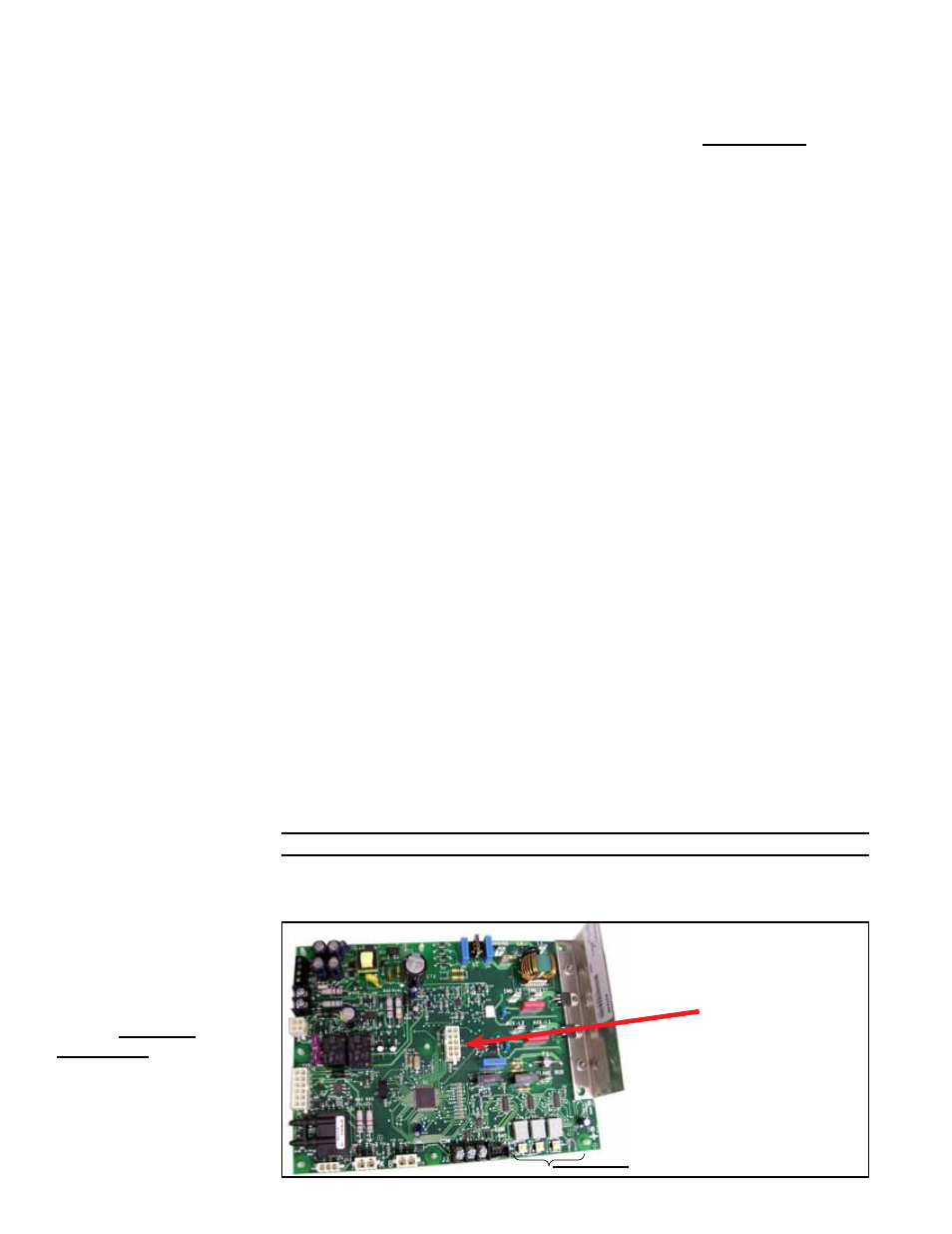
FIGURE 42 - Ignition
Control Module with
Display in the Electrical
Compartment -
MAPS
®
Cabinets
A, B, and C
ID Plug
3-Digit Display
- REDB Unit Installation Manual RECB Unit Installation Manual RDDC Unit Installation Manual RDCC Unit Installation Manual RDDB Unit Installation Manual RDCB Unit Installation Manual RDC Unit Installation Manual RCC Unit Installation Manual RDB Unit Installation Manual RCB Unit Installation Manual REDC Unit Installation Manual MAPSIV Unit Installation Manual MAPSIII Unit Installation Manual