2 curb cap base and mounting, 3 mounting a horizontal discharge system, On cross supports - d cabinet only – Reznor RECC Unit Installation Manual User Manual
Page 10: 4 mounting on a roof curb, 0 mounting (cont'd)
Form I-MAPSIII&IV, Page 10
5.4 Mounting on a
Roof Curb
MAPS
®
packaged heating/cooling systems have a curb cap base designed for use
with a full perimeter curb. When on a roof, either a manufacturer-designed roof curb, a
field-supplied roof curb, or other field-supplied support is required.
NOTE: A Reznor
®
roof curb is required with a vertical discharge and/or bottom return air to provide a
weatherproof installation.
A MAPS
®
III Cabinet D size system which has an optional horizontal discharge may be
set directly on a concrete slab or cross supports (See Paragraph 5.3 below).
5.2 Curb Cap Base
and Mounting
MUST be sealed
between curb cap
rail and roof curb.
Optional or
Field-Supplied
Roof Curb fits
under and inside
the curb cap.
Base of curb cap edge may be
set directly on a cement slab or
on perpendicular supports.
4-7/8”
(124mm)
Edge of curb cap extends
down over roof curb.
Cabinet W
all
Curb
Cap Rail
5.3 Mounting a
Horizontal
Discharge
System on
Cross Supports
(no roof curb) -
D Cabinet only
Prior to installation, be sure that the method of support is in agreement with all local
building codes and is suited to the climate. If considering an installation without a roof
curb in snow areas, the support under the system should be at least 12” (305mm)
higher than the roof surface.
IMPORTANT NOTE: If setting cross supports on the roof
surface and not decking, be sure to have sufficient tread material under the supports to
adequately spread the load and prevent “sinking” into the roofing material.
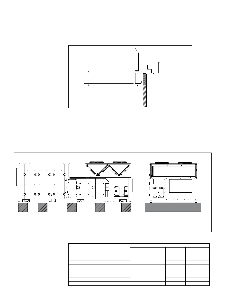
The field supplied, weather resistant, cross-support structure must be secure and
adequate for the weight of the system (Refer to weights in Paragraph 5.1). See width
dimensions in Paragraph 4.2.
Damper Access
Coil Access
Fan & Motor
Access
Control Access
Heat Access
Heat Access
FRONT VIEW
SIDE
VIEW
There MUST be no less than five cross supports. A cross support MUST be in the approximate
locations shown in the Side View. ALL cross supports MUST extend the full width of the unit as shown
in the Front View. Cross supports must be weather resistant and must be able to support the unit weight.
Supports should be a minimum height of 12” (305mm) in snow areas.
Horizontal
Discharge
Cross Supports
2
3
5
1
4
FIGURE 6 - Cross Support Requirements (no roof curb) - Cabinet D
Curbs available with the system are fully enclosed and insulated. Other characteristics
by cabinet size and option are listed below.
FIGURE 5 - Cross
Section View of Curb
Cap Base
5.0 Mounting
(cont'd)
*For cross-reference of
cabinet size to Model Size,
see Appendix, pages 71-72.
MAPS
®
Cabinet Size*
Roof Curb
Discharge
Option
Height
A, B, & C
Down with Duct
Connections in the
Curb
CJ31
14" (356mm)
A, B, & C w/Energy Recovery Module
CJ34
D
CJ3
16" (406mm)
A & B
Horizontal Duct
Connections in the
Curb (at the inlet air
side of the unit)
CJ50
32" (813mm)
C
CJ49
36" (914mm)
A & B w/Energy Recovery Module
CJ54
32" (813mm)
C with Energy Recovery Module
CJ53
36" (914mm)
D - horizontal discharge connection on unit (no return air)
CJ3
16" (406mm)
- REDB Unit Installation Manual RECB Unit Installation Manual RDDC Unit Installation Manual RDCC Unit Installation Manual RDDB Unit Installation Manual RDCB Unit Installation Manual RDC Unit Installation Manual RCC Unit Installation Manual RDB Unit Installation Manual RCB Unit Installation Manual REDC Unit Installation Manual MAPSIV Unit Installation Manual MAPSIII Unit Installation Manual