0 controls (cont'd) – Reznor RECC Unit Installation Manual User Manual
Page 46
Form I-MAPSIII&IV, Page 46
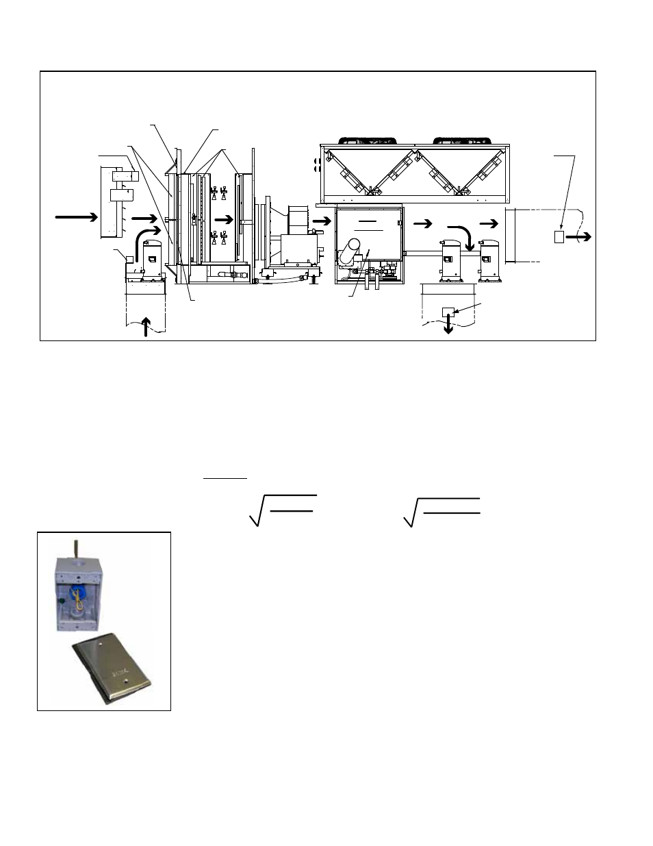
Outside
Air
Return
Air
Mixed Air Averaging
Sensor (between
filters and coil)
Return Air
Sensor
Temperature/
Humidity
Outside
Air Sensor
Temperature/
Humidity
Filters
Dirty Filter Switch Sensor
(entering air side)
Dirty Filter Switch Sensor
(leaving air side)
Coils
Air Proving
Switch Tap
Heat
Section
Discharge Temperature
Sensor (field installed;
see Paragraph 8.1.1)
Discharge
Temperature
Sensor (field
installed; see
Paragraph
8.1.1)
Vertical
Discharge
Horizontal
Discharge
Condenser Section
FIGURE 25 - Airflow and Sensor (std & some optional) Locations - D Cabinet
illustrated
8.1.1 Instructions for
Installing Discharge
Air Sensor in the
Ductwork
FIGURE 26 -
Discharge Air
Temperature
Sensor Probe and
Weatherproof Box,
P/N 222753
The discharge air temperature sensor (See
FIGURE 26.) is shipped with every unit
and must be field installed in the ductwork. The location and position of the sensor are
important. Follow the instructions below.
1. Determine the appropriate distance from the unit. Be sure there is sufficient
distance from the outlet to have a good mixture of discharge air temperature.
According to the latest edition of AMCA Standard 201, in straight ducts, the air
is typically well mixed a minimum of five equivalent duct diameters from the dis-
charge of the unit with equivalent duct diameter defined as equal to the square
root of 4AB/3.14. "A" and "B" are the duct cross-sectional dimensions.
Example: Supply ductwork cross-sectional dimension is
24" x 12" (610mm x 305mm).
5 x
4 x 12 x 24
3.14
= 96"
5 x
4 x 305 x 610
3.14
= 2435mm
Locate the sensor a minimum of 96" (2435mm) from the
outlet of the unit.
NOTE: If the length of the discharge duct is less than 8 ft (2.4M), a mixing vane is
recommended for mixing the discharge air.
Do not mount the sensor in the ductwork after a split in the supply as that will
cause loss of control in the duct that does not house the sensor.
2. Determine the location and orientation of the sensor. The position of the sen-
sor in the duct is also important. In horizontal ductwork, locate the sensor assem-
bly in the top, middle of the duct with the sensor probe extending vertically down
into the center of the airstream.
In vertical ductwork, locate the sensor assembly in the middle of the side of the
duct that corresponds with the top middle of the discharge outlet.
3. Attach the sensor. Mark the selected location and drill a 7/16" hole. Insert the
probe into the hole. Be sure that the blue plastic fitting holding the probe is cen-
tered in the hole. Attach with two No. 8 sheetmetal screws (do not overtighten).
Check to be certain that the hole is sealed.
4. Run the sensor wire to the unit. Use field-supplied 2 to 3 pair of 16 to 22 ga
wire. Digital control inputs are low-current, resistance-based signals. For optimum
temperature control performance, it is recommended that the sensor inputs (zone
8.1 Cooling/ Dehumidification/Heating Control (cont'd)
8.0 Controls
(cont'd)
- REDB Unit Installation Manual RECB Unit Installation Manual RDDC Unit Installation Manual RDCC Unit Installation Manual RDDB Unit Installation Manual RDCB Unit Installation Manual RDC Unit Installation Manual RCC Unit Installation Manual RDB Unit Installation Manual RCB Unit Installation Manual REDC Unit Installation Manual MAPSIV Unit Installation Manual MAPSIII Unit Installation Manual