2 optional unit monitoring sensors – Reznor RECC Unit Installation Manual User Manual
Page 47
Form I-MAPSIII&IV, P/N 222917R9, Page 47
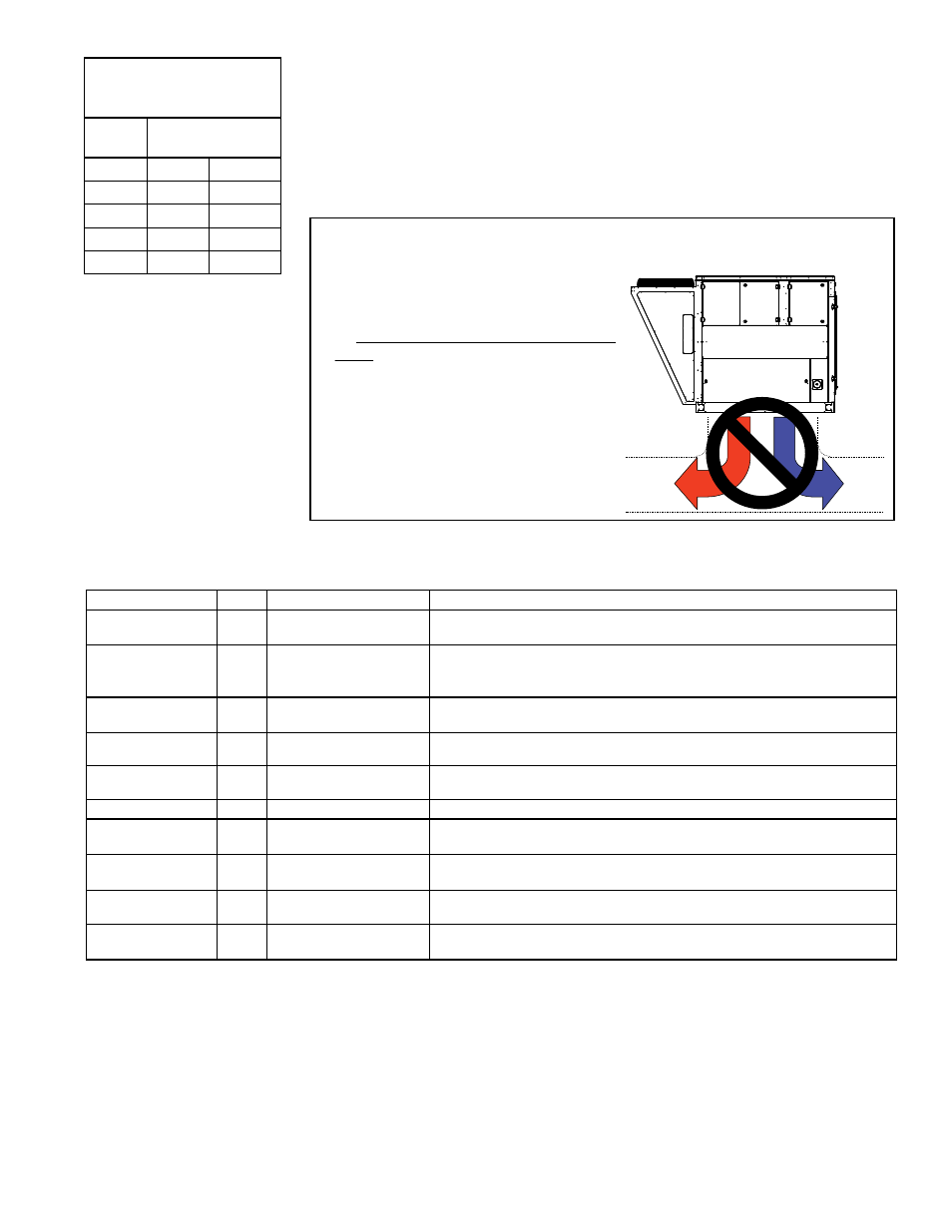
Maximum Sensor Wire
Length for less than 1°F
Signal Error
Wire
Gauge
Maximum Sensor
Wire Length
AWG
Feet
Meters
16
500
152
18
310
94
20
200
61
22
124
38
Electric Heat
Section
Hot
Air
Cool
Air
If a Model RECB, REDB, RECC, with multi-stage
control is installed in a system with immediate
“T” configuration ductwork leaving the discharge,
heat staging may allow stratification of the air.
The result is hot air only moving down one
segment of the duct while cool air moves
down the other segment. Avoid this application.
If this application is not avoidable, provide air
mixing devices or the necessary duct length
before the “T” for mixing of the discharge air.
Specific requirements for locating
discharge air sensor on electric heat
models:
FIGURE 27 - Sensor Location for Units with an Electric Heat Section
with Stage Control
sensors, discharge air sensors, etc.) that are connected to the controller be routed
to the unit in one of the following manners:
• In separate field-supplied conduits, isolated from 24 VAC controls and line volt-
age power to the unit,
OR
• If the sensor wires are to be run in the same field-supplied conduit as 24 VAC
control wiring, use shielded cable and bundle wires separately from 24 VAC
control wiring. The shield must be drained at the unit and taped on the opposite
end.
8.1.2 Optional Unit
Monitoring Sensors
In addition to the standard sensors, the unit may be equipped with the following optional
unit monitoring sensors: Most are factory installed but some require field installation.
Follow the sensor wiring requirements above for wiring field-installed sensors.
Senses
Option Components
Installation and Function
Evaporator Coil
Temperature
BE9
Sensor,
P/N 223111
Factory installed sensor to monitor and control the temperature of the air
as it exits from passing through the evaporator coil.
Mixed Air
Temperature
BE10 Sensor,
P/N 223111
Factory installed sensor between the filters and the evaporator coil to
monitor the temperature of the "mixed air" entering from both outside and
through the return air opening.
Duct Static
Pressure
BE11 Transducer, P/N 234818;
sensor port, P/N 234821
Factory installed transducer to monitor duct pressure. Requires field
installation of pickup and tubing in the supply duct. See instructions below.
Building Static
Pressure
BE12 Transducer, P/N 234819 Factory installed transducer to monitor building pressure. Requires field
installation of field-supplied pickup(s) and tubing. See instructions below.
Return Air
Temperature
BE13 Sensor,
P/N 222753
Field installed in the return air duct to monitor the temperature of return air
entering the unit.
Return Air Humidity
BE14 Sensor, P/N 234907
Field installed to monitor the humidity of return air entering the unit.
Space CO
2
, Range
0
to
2000 ppm
BE15 Sensor,
P/N 234820,
Field installed in the building to monitor the carbon dioxide level. See
instructions below and in the sensor manufacturer's form.
Filter Pressure
BE16 Sensor,
P/N 255784
Factory installed photohelic pressure sensor monitors pressure through
the filters and send a signal to the IQ Controller.
Duct Smoke
Detector
BE17 Smoke Detector, P/N
159553
Field installed photohelic smoke detector in the supply ductwork. See
instructions below and in the manufacturer's installation form.
Filter Pressure
BE16 Pressure Switch, P/N
105507
Factory installed pressure switch monitors pressure drop through the
filters and sends signal to I/Q Controller.
Option BE11, Duct Static Pressure Sensor
The differential pressure transducer (
P/N 234818) used in Option BE11 is mounted in
the low voltage compartment. A data sensor port is shipped loose to be attached to
the side of the ductwork. To install the duct sensor port, locate a position about 2/3 the
distance of the duct run (minimum of 10 duct lengths). Drill a hole in the side of the
duct, insert the sensor tube and attach with four sheetmetal screws. The transducer
has a high and a low tubing port. The low tubing port will remain open to measure
atmospheric pressure. Connect 1/4" field-supplied tubing to the high pressure port and
to the field-installed sensor port. The transducer has a range of 0 to 2.5" w.c. and was
calibrated at the factory; it should not need field adjustment. Refer to the manufac-
turer's instructions in the owner's envelope for additional information.
Instructions for Field-
Installed Sensors in
Table above
- REDB Unit Installation Manual RECB Unit Installation Manual RDDC Unit Installation Manual RDCC Unit Installation Manual RDDB Unit Installation Manual RDCB Unit Installation Manual RDC Unit Installation Manual RCC Unit Installation Manual RDB Unit Installation Manual RCB Unit Installation Manual REDC Unit Installation Manual MAPSIV Unit Installation Manual MAPSIII Unit Installation Manual