Mechanical (cont'd), 3 outside air hood (cont'd), 2 option as16, inlet air hood for maps – Reznor RECC Unit Installation Manual User Manual
Page 34: Iii "d" cabinet, 1 air hoods for maps, Iii a, b, & c cabinets (cont'd), Iii d cabinet
Form I-MAPSIII&IV, Page 34
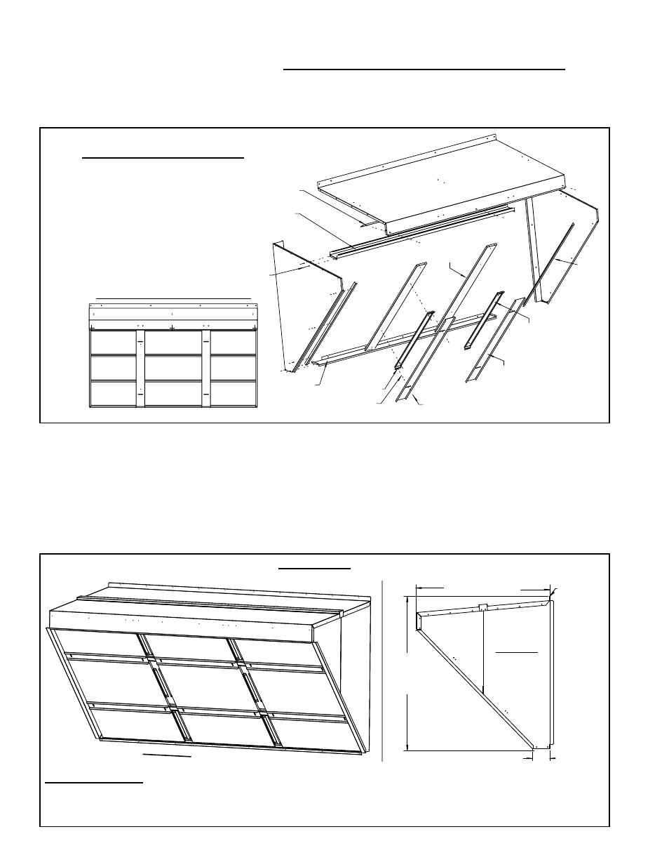
6.3.2 Option AS16,
Inlet Air Hood for
MAPS
®
III "D" Cabinet
Installation Instructions for Inlet Air Hood Option AS16 for D Cabinet
Models
To avoid possible damage, it is recommended that the outside air hood be installed
after the system has been placed on the roof. The air hood should be installed before
the blower is operated. Do not install the hood while the system is in operation. Due to
the size, assembly and installation requires two persons.
6. Mechanical
(cont'd)
6.3 Outside Air
Hood (cont'd)
Filter
16x20x1
Filter
16x20x1
Filter
16x20x1
Filter
16x25x1
Filter
16x25x1
Filter
16x25x1
Filter
16x20x1
Filter
16x20x1
Filter
16x20x1
Inlet View Showing Filter Arrangement
Top, P/N 255207
(Slide edge of top under cabinet top.)
Top Support,
P/N 208636
V
ertical Filter
Supports,
(2) P/N 208632
Sheetmetal
Screws,
P/N 11813
Right Side,
P/N 208629
Left Side,
P/N 208630
Filter
Angles
(2) P/N
208635
Filter Clamp
(2) P/N 208634
Bottom,
P/N 208631
Clip-on
Receptacle
for Wing Screw
(4) P/N 205708
Nylon Retainer for Wing
Screw (4) P/N 205709
Wing Head Screw
(4) P/N 205707
Top Filter Filler,
P/N 210146
Filter Spacer
(2) P/N 208633
FIGURE 17D - Installation of Outside Air
Hood, Option AS16 or Option AS19, on
MAPS
®
III Cabinet C Models
For a cross-reference of
cabinet size and model size,
refer to the Appendix,
pages 71-72.)
FIGURE 17D - Cabinet Size C with or without a power exhaust option - Attach
the top filter filler, the two vertical filter supports and the two side filter angles.
Attach the two inner filter spacers with wing screw receptacles. Position the nine
filters in the opening as shown. Secure the filters with the filter clamps and the
wing screws.
6.3.1 Air Hoods for MAPS
®
III A, B, & C Cabinets (cont'd)
Installation NOTES:
- Select screws carefully. Use sheetmetal screws (slotted head with straight tip) when holes in the cabinet are
provided. Use self-drilling screws (head is not slotted with drill-type tip) when matching holes are not provided.
- Follow STEPS in order.
FIGURE 18A - Assembled Inlet Air Hood, Option AS16 for MAPS
®
III D Cabinet
48-11/32” (1228mm)
54-1/4”
(1378mm)
6-1/4” (159mm)
Dimension
from top of
unit and
rear panel.
Side View
of Installed
Hood
(2) P/N 104102,
16x16x1
(2) P/N 104102,
16x16x1
(2) P/N 104102,
16x16x1
(2) P/N 104102,
16x16x1
(2) P/N 104102,
16x16x1
(2) P/N 104102,
16x16x1
(2) P/N 101609,
16x25x1
(2) P/N 101609,
16x25x1
(2) P/N 101609,
16x25x1
Inlet View of Installed Hood
- REDB Unit Installation Manual RECB Unit Installation Manual RDDC Unit Installation Manual RDCC Unit Installation Manual RDDB Unit Installation Manual RDCB Unit Installation Manual RDC Unit Installation Manual RCC Unit Installation Manual RDB Unit Installation Manual RCB Unit Installation Manual REDC Unit Installation Manual MAPSIV Unit Installation Manual MAPSIII Unit Installation Manual