5 rigging and lifting the maps, Units, 0 mounting (cont'd) – Reznor RECC Unit Installation Manual User Manual
Page 28
Form I-MAPSIII&IV, Page 28
Installing Ductwork with
Option CJ3 MAPS
®
III
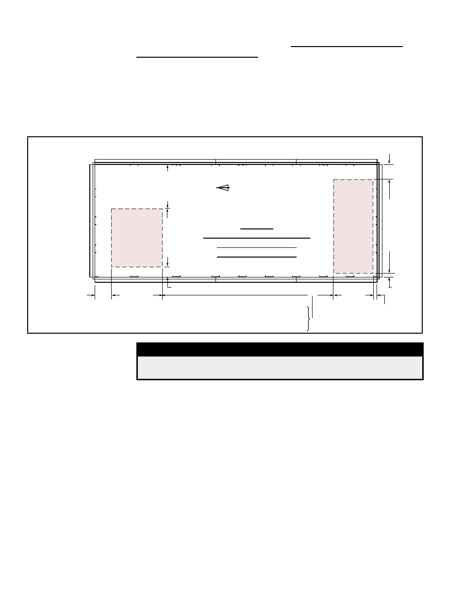
Cabinet D Roof Curb
The roof curb designed for the MAPS
®
D Cabinet
includes return air and discharge
duct supports that allow the ductwork to be inserted down through the roof. The sizes
of the duct openings are shown in
FIGURE 12E. Ductwork should be sized slightly
smaller with a minimum 3/4" duct flange that can be attached to all sides of the duct
connection. The duct opening is positioned to mate with the heater inlet or discharge.
After installing the ductwork, before placing the system on the curb, apply sealant tape
to the top surface of the duct opening sides making good butt joints at the corners.
(Sealing tape must also be applied to the curb rails.)
47-1
1/16”
(121
1mm)
Unit Airflow
Size of
Discharge
Duct Opening
for inserting
ductwork down
through
the roof curb.
Size of Return
Air Duct
Opening for inserting ductwork down through
the roof curb.
19-7/8”
(505mm)
26-3/4”
(679mm)
72” (1829mm)
4-7/16”
(113mm)
12-9/16”
(319mm)
35-21/32” (906mm)
4-1/2”
(114mm)
12-3/4” (324mm)
Top View
Showing Duct Opening Sizes
and Perimeter only of
Option CJ3 Roof Curb
5-21/32” (144mm)
RCB, RDB, RECB, REDB - All Sizes - 133-5/16” (3386mm)
RDCB, RDDB with Heat Sections 500, 600, 700, 800 - 133-5/16” (3386mm)
RDCB, RDDB with Heat Sections 1000, 1200, 1400, 1600 - 165-3/4” (4210mm)
FIGURE 12E - Duct Opening Dimensions and Locations inside Option CJ3 Roof Curb for
MAPS
®
III Cabinet D
5.0 Mounting
(cont'd)
5.4.4.Roof Curbs for MAPS
®
Models RCB, RDB, RDCB, RDDB,
RECB, REDB Cabinet Size D (cont'd)
5.4 Mounting on a Roof Curb (cont'd)
5.5 Rigging and
Lifting the
MAPS
®
Units
DANGER
If there is any visible damage or any question about the integrity
of a lifting point, DO NOT LIFT the system. Consult the factory.
See approximate net weights in Paragraph 5.1. If corner weights are required, refer to
Sales/Technical Catalog Form C-PC (available at www.RezSpec.com).
IMPORTANT
NOTE: ALL MAPS
®
Cabinet C and D systems MUST be loaded and unloaded by lift-
ing. Due to size, DO NOT attempt to move any MAPS
®
C or D Cabinet with a fork lift.
Holes for attaching rigging are provided in the base. Cabinets A, B, and C have four
lifting holes -- one on each corner; see
FIGURE 14A. Cabinet D has six lifting holes for
rigging; see
FIGURE 14B. ALL lifting points MUST always be used. Spreader bars
MUST be used to prevent cabinet damage.
Failure to lift by the manufacturer's instructions could cause damage to the equipment
and/or personal injury or death. The equipment manufacturer is not responsible for
unsafe rigging or lifting procedures.
The unit MUST be rigged with spreader bars that will allow the unit to be lifted straight
up with vertical force only on the lifting points. Using ALL lifting points is mandatory.
In addition to checking the rigging, before lifting the unit, verify the following:
□
If the unit is being set on a down discharge curb and ductwork is being installed
from the top, verify that the ductwork is installed.
□
If installing an Option JH duct furnace curb section, verify that sealant tape has
been applied to all top surfaces of the curb. Verify the orientation so that the
openings match. Set the duct furnace section on the roof curb before the unit.
- REDB Unit Installation Manual RECB Unit Installation Manual RDDC Unit Installation Manual RDCC Unit Installation Manual RDDB Unit Installation Manual RDCB Unit Installation Manual RDC Unit Installation Manual RCC Unit Installation Manual RDB Unit Installation Manual RCB Unit Installation Manual REDC Unit Installation Manual MAPSIV Unit Installation Manual MAPSIII Unit Installation Manual