3 outside air hoods, Mechanical (cont'd) – Reznor RECC Unit Installation Manual User Manual
Page 32
Form I-MAPSIII&IV, Page 32
6.3 Outside Air Hoods
All inlet air hoods (Option AS16 or AS19) require field installation. Hood instructions
differ for Cabinets A, B, C, and D. Follow the illustrated instructions that apply.
The outside air inlet hood is a weatherized hood with permanent aluminum filters,
designed to be field assembled and installed around the horizontal inlet air opening of
the cabinet (either the MAPS
®
unit or an optional energy recovery module).
CAUTION: It is recommended that the inlet to the outside air
hood NOT be facing into the prevailing wind. Allow 14" minimum
clearance from the bottom of the air hood to the mounting surface.
To avoid possible damage, it is recommended that the outside air hood be installed
after the system has been placed on the roof. The air hood should be installed before
the blower is operated. Do not install the hood while the system is in operation. All
screw ends should be inside the air hood.
NOTE: If equipped with a power exhaust option (Option PE), attach the power exhaust
hoods
BEFORE installing the inlet hood for outside air.
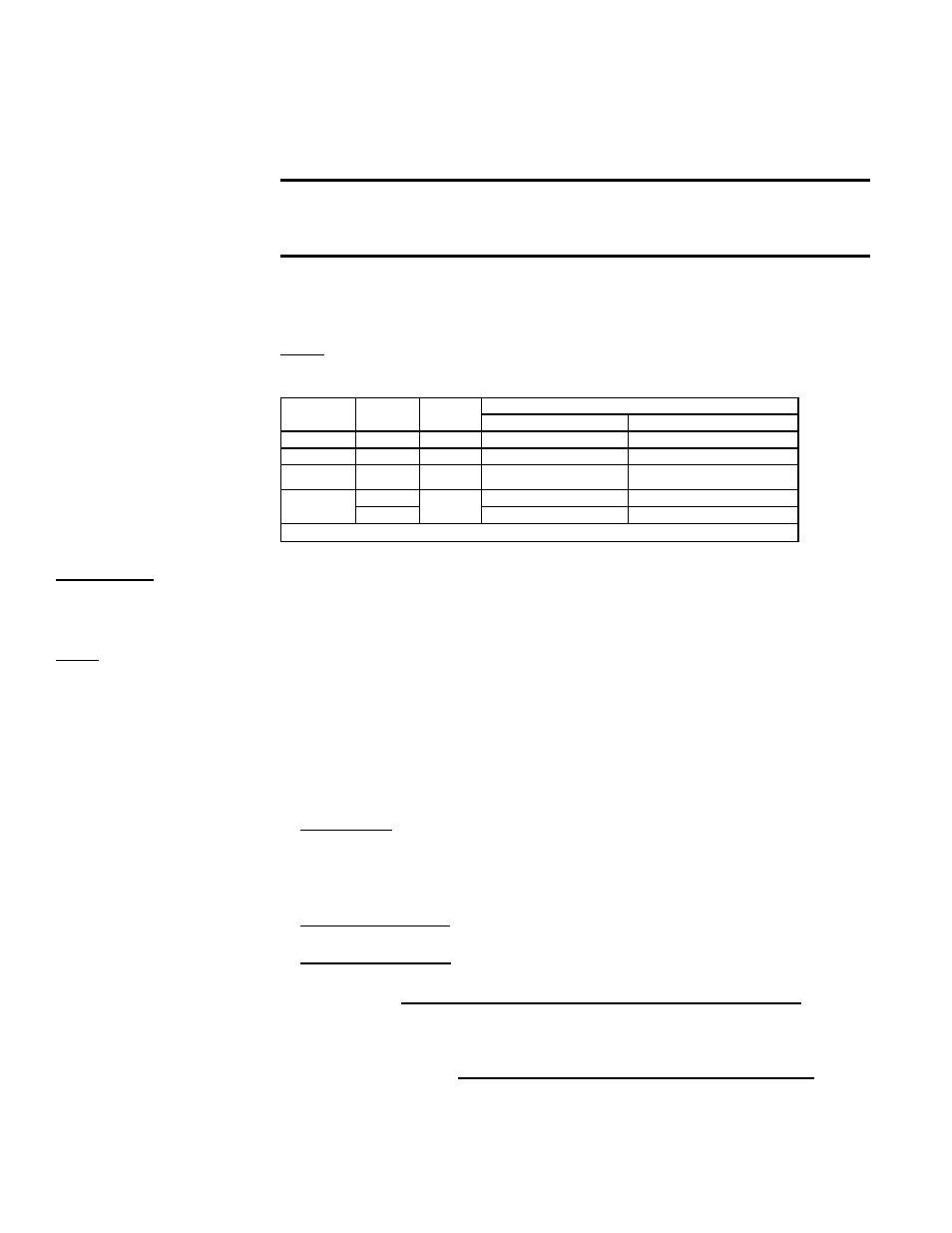
Refer to the illustration that applies:
Refer to
FIGURE
Hood
Option
MAPS®
Size *
May be used with optional equipment::
Power Exhaust (PE)
Energy Recovery (ER1)
17A
AS16
A, B
no
no
17B
AS19
A
yes
yes
17C
AS19
B
yes
yes
17D
AS16
C
no
no
AS19
yes
yes
*
See Model Size/Cabinet Size cross-reference on pages 71-72.)
6.3.1 Option AS16 or
AS19, Inlet Air Hood
for MAPS
®
III A, B, and
C Cabinets
NOTE: Other inlet air
options may also require
field installation. See Para-
graph 9.1 for information
on other optional inlet air
accessories.
Instructions (apply to
all FIGURES 17A-D
except where noted):
NOTE: Select screws
carefully. Use sheetmetal
screws (slotted head with
straight tip) when holes in
the cabinet are provided.
Use self-drilling screws
(head is not slotted with
drill-type tip) when cabinet
holes are not provided.
6. Mechanical
(cont'd)
1. Install Top Panel - On the air inlet of the cabinet, remove and save the factory-
installed screws attaching the system top. Slide the hood
top panel underneath the
edge of the cabinet top.
The edge of the hood top panel must be between the
cabinet top and the end panel. Reinsert all of the sheetmetal screws.
2. Install Left Side Panel (right when facing the unit) - Locate the vertical row
of cabinet screws to the right of the opening that attach the condenser section.
Remove and save those screws.
Position the hood left side panel under and to the
inside of the hood top panel.
Reinsert the screws to attach the side panel.
Attach the hood side panel to the hood top with sheetmetal screws.
3. Install Right Side Panel (left when facing the unit) - Position the hood right side
panel under and to the inside of the hood top panel. Attach to the unit using the
required number of
self-drilling screws.
4. FIGURE 17C - Install Top Panel Slope Section - Position the slope panel against
the top panel and over the side panels. Attach to the top panel and both sides with
sheetmetal screws.
5. Install Bottom Support - Position the hood bottom support so that it is to the
inside of the two side panels.
FIGURES 17A & 17D - Attach to the cabinet using the required number of self-
drilling screws. Attach to both side panels with sheetmetal screws.
FIGURES 17B & 17C - Attach to both side panels with sheetmetal screws.
6. Install the Filter Assembly
FIGURE 17A, Cabinet Sizes A and B without a power exhaust option -
Attach the center support and the two side filter angles. Attach the filter spacer
with wing screw receptacle. Position the four filters in the opening. Secure the fil-
ters with the filter clamp and the wing screws.
FIGURES 17B & 17C, Cabinet Size A or B with a power exhaust option -
Install the filter frame with filters in place. Position the filter frame assembly in the
inlet opening of the hood. Attach at the front and back holes with 1/2" sheetmetal
screws. Insert a 3/4" sheetmetal screw at each of the center holes (one on each
side.
- REDB Unit Installation Manual RECB Unit Installation Manual RDDC Unit Installation Manual RDCC Unit Installation Manual RDDB Unit Installation Manual RDCB Unit Installation Manual RDC Unit Installation Manual RCC Unit Installation Manual RDB Unit Installation Manual RCB Unit Installation Manual REDC Unit Installation Manual MAPSIV Unit Installation Manual MAPSIII Unit Installation Manual