0 optional equipment (cont'd) – Reznor RECC Unit Installation Manual User Manual
Page 58
Form I-MAPSIII&IV, Page 58
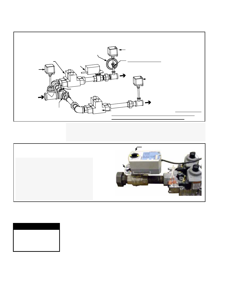
FIGURE 39 - Modulating Gas Control Manifold showing Two Furnaces - D Cabinet Sizes 1000,
1200, 1400, 1600 (See NOTE below.)
Optional Low
Gas Pressure
Switch
Manual Shutoff Valve
(2nd furnace)
Manual Shutoff Valve
(1st furnace)
Dual,
Single-Stage
Gas Valve
(1st furnace)
Dual, Single-Stage Gas Valve (2nd furnace) Measure manifold
pressure at the outlet taps in this valve; see FIGURE 41B,
page 40, and follow instructions beginning below.
Optional High Gas Pressure
Switch (1st furnace)
Manifold Pressure TAP
(1st furnace)
Optional High Gas
Pressure Switch
(2nd furnace)
To burner on
1st furnace
To burner on
2nd furnace
Gas
Supply
Ball Valve
with Actuator
(1st furnace)
(See FIGURE 31.)
Pressure Switch
(1st furnace)
NOTE: "D" Cabinets with Heat section Sizes 500, 600, 700, and 800 with
one furnace have the manifold for "1st furnace" only. "D" Cabinets with
two furnaces (Heat Section Sizes 1000, 1200, 1400, and 1600) have two
manifolds as shown in FIGURE 39.
9.2 Gas Heat - Models RDCB, RDDB, RDCC, RDDC (cont'd)
9.0 Optional
Equipment
(cont'd)
9.2.1.2 Gas Piping and Pressures (cont'd)
9.2.1 Gas Heat Module - Mechanical (cont'd)
FIGURE 40 - Actuator and Ball Valve in
Modulating Gas Control Option AG70
Single-Stage or Dual Single-Stage
Valve
If manifold pressure adjustment is
required, outlet pressure of the single-
stage gas valve (either regular or dual)
must be adjusted. See
FIGURE 41A or
41B and follow instructions for adjusting
the single stage valve
.
Ball Valve Actuator
Setscrew
Ball Valve
Manifold Pressure
Measuring and
Adjustment
The valves are normally set at the factory to provide 3.5" w.c. manifold pressure on a
demand for high fire.
Measuring manifold gas pressure cannot be done until the heat section is in operation.
It is included in the steps of the "Check-Test-Start" procedure in Paragraph 10. The
following warnings and instructions apply.
NOTE: Manifold pressure is checked at high fire. If the heat section has two furnaces,
measure manifold pressure of both furnaces at the same time.
WARNING
Manifold gas
pressure must never
exceed 3.5" w.c. for
natural gas.
CAUTION: DO NOT bottom out the gas valve regulator adjusting
screw. This can result in unregulated manifold pressure causing
excess overfire and heat exchanger failure.
Instructions for Measuring High Fire Manifold Pressure (can only be
done after the heater is operating)
1) Turn the manual valve in the gas line off. Locate the tap(s) for testing pressure.
See
FIGURES 38 A, B, C or 39.)
- REDB Unit Installation Manual RECB Unit Installation Manual RDDC Unit Installation Manual RDCC Unit Installation Manual RDDB Unit Installation Manual RDCB Unit Installation Manual RDC Unit Installation Manual RCC Unit Installation Manual RDB Unit Installation Manual RCB Unit Installation Manual REDC Unit Installation Manual MAPSIV Unit Installation Manual MAPSIII Unit Installation Manual