2 storage, 0 clearances and dimensions, 1 clearances – Reznor RECC Unit Installation Manual User Manual
Page 6: 0 receiving and storage (cont'd)
Form I-MAPSIII&IV, Page 6
4.0 Clearances
and
Dimensions
3.2 Storage
If this system is going to be stored, take precautions to prevent condensate formation
inside the electrical compartments and motors. To prevent damage to the unit, do not
store sitting on the ground.
Battery backup for controls will maintain for approximately one year. If backup expires,
controls will need to be reprogrammed.
3.0 Receiving
and Storage
(cont'd)
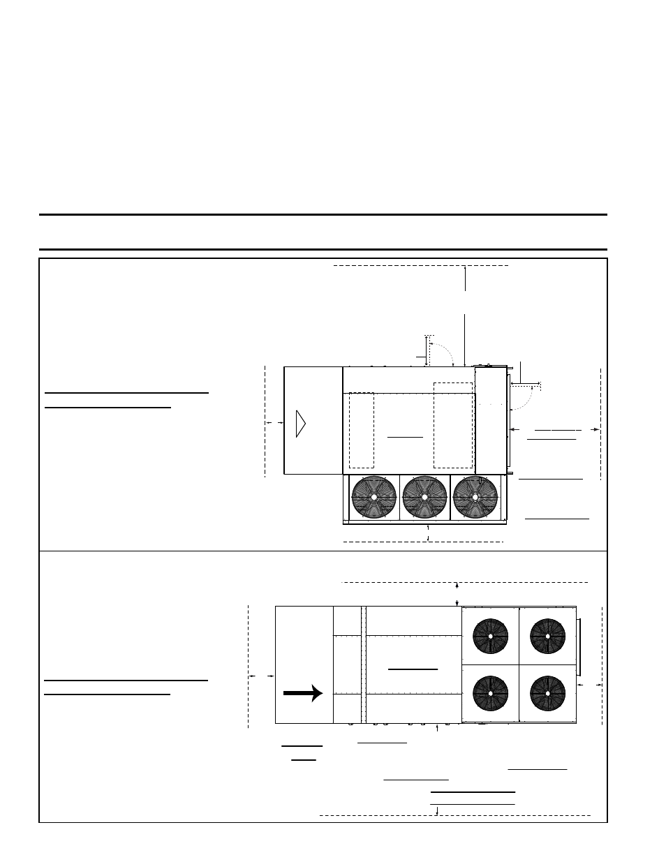
Provide minimum clearances as shown in
FIGURE 2A or 2B. Minimum clearances
are required to ensure proper operation and access for service. If a heat section is
included, clearance to combustibles is required. Clearance to combustibles is defined
as the minimum distance from the heater to a surface or object that is necessary to
ensure that a surface temperature of 90°F (50°C) above the surrounding ambient tem-
perature is not exceeded.
4.1 Clearances
FIGURE 2A - MAPS
®
A, B, & C Cabinet Clearances
For cross-reference of cabinet size to model
size, see APPENDIX, pages 71-72.
Top Clearance: All Models - 60"
(1524mm)
Bottom Clearance: All Models - 0"
(0mm)
Additional Gas Heat Section
Clearance Information
If installing a unit with a gas heat
section, the 40" (1016mm) service
clearance provides for clearance to
combustibles and required space for
combustion air inlet and venting. Vent
terminal must be 4 feet (1.22M) from
gas and electric meters, regulators,
and relief equipment.
FIGURE 2B - MAPS
®
III D Cabinet Clearances
For cross-reference of cabinet size to model
size, see APPENDIX, pages 71-72.
Top Clearance: All Models - 60"
(1524mm)
Bottom Clearance: All Models - 0"
(0mm)
Additional Gas Heat Section
Clearance Information -
If installing a unit with a gas heat
section, the 4 ft 7 inch (1.4M)
service clearance provides for
clearance to combustibles and
required space for combustion air
inlet and venting. Vent terminal
must be 4 feet (1.22M) from gas
and electric meters, regulators,
and relief equipment.
Bottom Supply
Air Opening
Bottom Return Air Opening
Outside Air
Hood
Top View
Airflow
All Models with
gas or electric heat
- Clearance to
Combustibles -
4 ft (1.22M)
Models RDCB, RDCC,
RDDB & RDDC -
Service Clearance is
4 ft 7 inches (1.4M)
Models RECB, RECC,
REDB & REDC
- Service Clearance
is 4 ft (1.22M)
Door Width (largest door)
Cabinet A, 23” (584mm)
Cabinet B, 27“ (686mm)
Cabinet C, 32” (813mm)
Door Width (largest door)
Cabinets A&B, 26” (660mm)
Cabinet C, 32-1/2” (826mm)
All Models - Minimum Service
Clearance - Width of the Unit
All Models - 24” (610mm)
All Models - 24” (610mm)
Outside
Air Hood,
Option
AS16
All Models - 24” (610mm)
All Models - 24” (610mm)
Models RDCB, RDDB, RECB, REDB - Clearance to
Combustibles - 40” (1016mm)
Models RDCB & RDDB - Service Clearance - 40” (1016mm)
Models RECB & REDB - Service Clearance - 64” (1626mm)
All Models - 87” (2210mm) is minimum clearance
to remove coil section sliding drain pan
Top View
Control
Side
Airflow
All Models - 24” (610mm)
IMPORTANT: The area above the condenser fans MUST ALWAYS be totally open
space to allow proper airflow through the condenser coils.
- REDB Unit Installation Manual RECB Unit Installation Manual RDDC Unit Installation Manual RDCC Unit Installation Manual RDDB Unit Installation Manual RDCB Unit Installation Manual RDC Unit Installation Manual RCC Unit Installation Manual RDB Unit Installation Manual RCB Unit Installation Manual REDC Unit Installation Manual MAPSIV Unit Installation Manual MAPSIII Unit Installation Manual