0 electrical and wiring (cont'd), 2 supply wiring (cont'd), Warning if the maps – Reznor RECC Unit Installation Manual User Manual
Page 42: 3 3-phase wiring check, 2 supply voltage, Figure 22 - disconnect wiring connections
Form I-MAPSIII&IV, Page 42
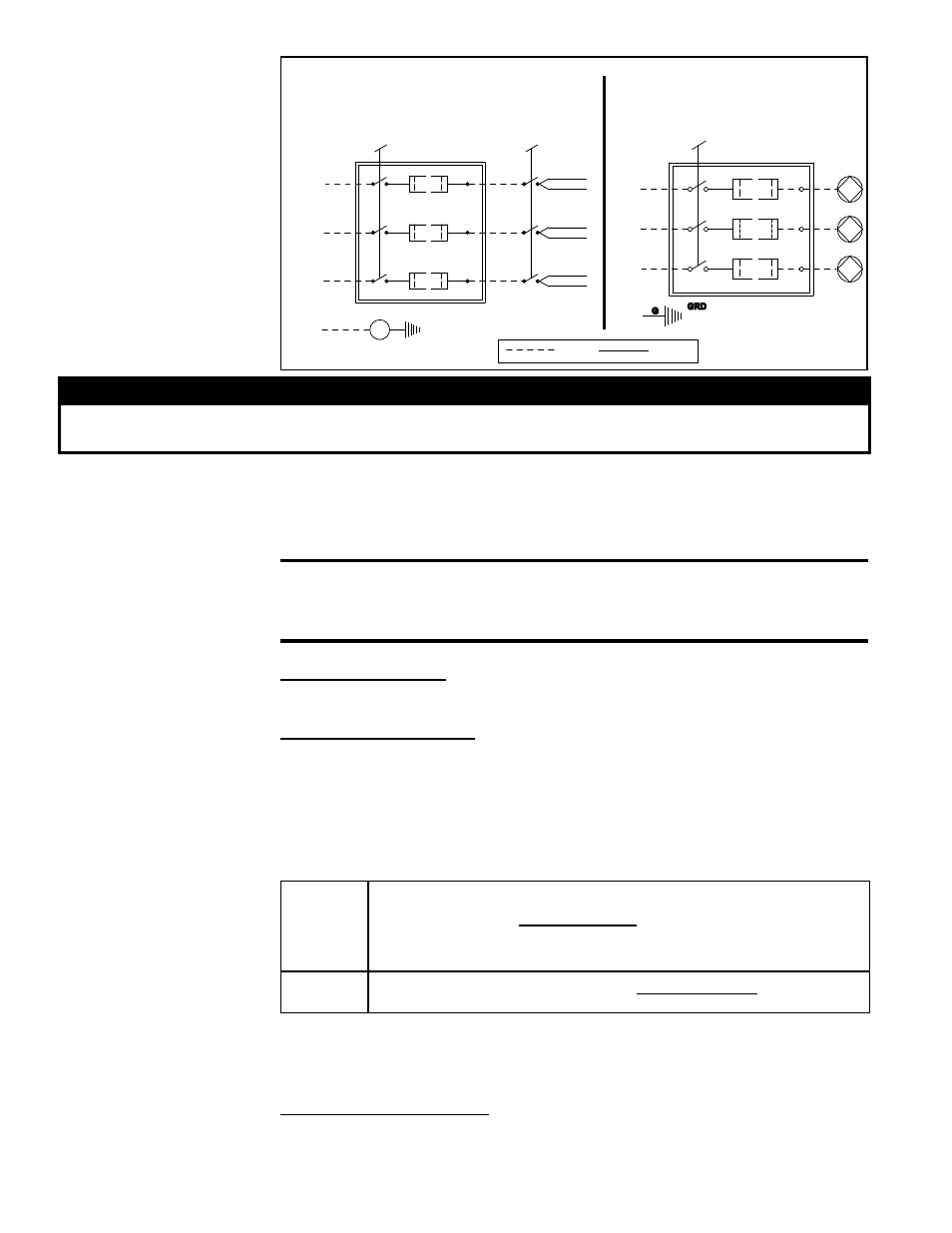
FIGURE 22 - Disconnect
Wiring Connections
BLACK
BLACK
L3
T3
GRD
L1
T1
L2
T2
Field-supplied or
Option CP
Disconnect
Switch
Field-supplied or
Option CP
Disconnect Switch
Unit-Mounted Option BA6 ON/OFF
Lockable Disconnect Switch
(Non-fusible, available only
with 460/3 or 575/3 supply)
Supply V
oltage
(See MCA
on rating plate to determine wire size.)
Supply V
oltage
(See MCA
on rating plate to determine wire size.)
YELLOW
YELLOW
RED
RED
Field
Factory
GRD
G
L1
L2
L3
(No Option BA6)
Option BA6 requires copper wiring with
ampacity based on 75°C maximum temp-
erature rating at the line side terminals.
WARNING
If the MAPS
®
unit includes a gas furnace, always turn off the gas when you turn off the
power supply.
7.0 Electrical and
Wiring (cont'd)
7.2 Supply Wiring
(cont'd)
7.2.3 3-Phase Wiring
Check
3-Phase Wiring Connection - There is a chance of unknowingly connecting
3-phase power in such a way as to cause compressor and blower rotation in
reverse. To prevent damage to the components, it is important to check this on
startup.
7.2.2 Supply Voltage
The electric supply to the unit must meet stringent requirements for the system to oper-
ate properly. Voltage supply should be within ±10% or as stated on the rating plate.
Maximum imbalance on a 3-phase system is 2%.
If the power supply is not within these tolerances, contact the power company prior to
operating the system.
CAUTION: If this unit is allowed to operate on an electric supply
that is not within the specified tolerances, the product warranty
shall be void.
Follow instructions below to check.
Check Voltage Supply - See voltage use range on the rating plate. Measure (and
record) each supply leg voltage at all line disconnect switches. Readings must fall
within the allowable range.
Check Voltage Imbalance - In a 3-phase system, excessive voltage imbalance
between phases will cause compressor motors to overheat and eventually fail. Maxi-
mum allowable imbalance is 2%. To determine voltage imbalance, use recorded volt-
age measurements taken above in the following formula.
NOTE: If the unit is equipped with Option PL4, an over/under voltage protection device,
the unit will shut down on an over or under voltage supply condition and also if there
is a phase loss. This is an auto reset device and will reset when the power condition
is corrected.
Key:
V1, V2, V3 = line voltages as measured
VA (average) =
(V1 + V2 + V3)
3
VD = line voltage (V1, V2, or V3) that deviates farthest from average (VA)
Formula:
% Line Voltage Imbalance =
[100 x (VA - VD)]
VA
Optional Voltage Protection, Option PL4 - If the system was ordered with Option
PL4 (identified on the wiring diagram), it will have a factory-installed redundant phase
loss/reversal and over/under voltage monitor. The monitor will cause the controller to
shut down the unit until the power condition is corrected. It is an automatic reset device.
- REDB Unit Installation Manual RECB Unit Installation Manual RDDC Unit Installation Manual RDCC Unit Installation Manual RDDB Unit Installation Manual RDCB Unit Installation Manual RDC Unit Installation Manual RCC Unit Installation Manual RDB Unit Installation Manual RCB Unit Installation Manual REDC Unit Installation Manual MAPSIV Unit Installation Manual MAPSIII Unit Installation Manual