0 optional equipment (cont'd), 1 inlet air options (cont'd) – Reznor RECC Unit Installation Manual User Manual
Page 54
Form I-MAPSIII&IV, Page 54
NOTE: To verify control
option selection, check the
option listing on the wiring
diagram and the option list
in the
APPENDIX, page 73.
Damper Linkage
Outside Air & Return Air Dampers, Option AR25, AR2G, AR2H, or
AR2K
- If outside and return air motorized dampers were ordered, there are a variety
of damper control options (Option GF). Some require field installation. If the damper
control sensing option requires field installation of components, the components are
shipped with the unit and include the manufacturer's instructions. Install according to
the instructions and connect the wires according to the unit diagram. Follow the same
wiring recommendations as in Paragraph 8.1.1 for the discharge air temperature sen-
sor.
When a system has both an outside air and a return air damper, both dampers are
closed for shipping. The linkage of the return air damper must be adjusted prior to use.
Follow instructions to adjust damper linkage.
1. Open the damper access door.
2. Loosen the setscrew on the return air damper rod at the damper arm.
3. Manually open the return air dampers. While the dampers are opening, the
damper rod and arm will automatically move to its correct position.
4. Tighten the setscrew.
5. Close the door.
9.0 Optional
Equipment
(cont'd)
9.1 Inlet Air Options (cont'd)
Senses
Option
Parts
Installation and Function
Remote Damper Control,
DDC
GF1 (requires
BHB6 Board)
Damper position is adjusted by the IQ controller in response to a field-
supplied remote 0-5V input signal. The I/Q controller limits the drive
speed between 25% to 100%.
Two Position Damper
Control (open/closed), DDC
GF2
Sends message to open or close dampers as required. Damper
opens to a fixed setpoint during occupied mode and closes during
unoccupied mode.
Four-Position Damper
Control
GF4 (requires
BHB6 Board)
Factory installed to provide four damper settings from two switches.
Each input represents a position. As the input changes, the I/Q
controller changes the damper position
Building Static Pressure
GF5 (requires
BHB6 Board)
Sensor, P/N
234819
Factory installed to monitor building pressure for damper operation.
Requires field-installation of sensor. See instructions below.
Mixed Air Controlled by
CO2 level
GF6 (requires
BHB6 Board)
Sensor, P/N
234820
Field installed in the building to monitor the carbon dioxide level. See
instructions below and in the sensor manufacturer's installation form
Outside Air Damper, 2-
Position Enthalpy Control
GF7
Factory installed to monitor the humidity of outside air entering the
unit.
Mixed Air Dampers, Dual
Reference Enthalpy Control
GF8 (requires
BHB6 Board
P/N 234907 Factory installed to measure enthalpy and provide information for
control of outside and return dampers.
Dry Bulb Mixed Air
Economizer
GF9
P/N 222753
and 223111
Factory installed to measure dry bulb temperature and provide
information for control of outside and return dampers.
Damper Control Options
Instructions for Field-
Installed Sensors in
Table Above
Option GF5, Building Static Pressure Sensor
The differential pressure transducer (
P/N 234819) used in Option GF5 is mounted in
the low voltage compartment. The transducer has a high and a low tubing port. The
low tubing port will remain open to measure atmospheric pressure. Connect 1/4" field-
supplied tubing to the high pressure port and run it to a common area in the building.
Cut the end of the tubing at a 45° angle to minimize the affect of air movement and
attach it to a wall or in a ceiling. The transducer has a range of 0 to .5" w.c. and was
calibrated at the factory; it should not need field adjustment.
Refer to the manufacturer's instructions in the owner's envelope for additional informa-
tion.
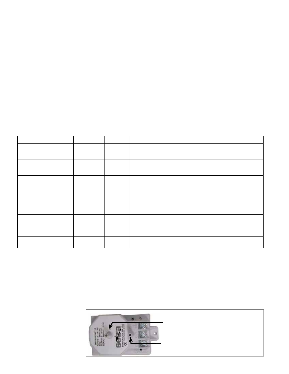
FIGURE 35A -
Electrical Connections
and Tubing Ports on
Option GF5, Building
Static Pressure Sensor
High Pressure Port - Attach tubing.
Low Pressure Port - Leave open.
- REDB Unit Installation Manual RECB Unit Installation Manual RDDC Unit Installation Manual RDCC Unit Installation Manual RDDB Unit Installation Manual RDCB Unit Installation Manual RDC Unit Installation Manual RCC Unit Installation Manual RDB Unit Installation Manual RCB Unit Installation Manual REDC Unit Installation Manual MAPSIV Unit Installation Manual MAPSIII Unit Installation Manual