Reznor RECC Unit Installation Manual User Manual
Page 61
Form I-MAPSIII&IV, P/N 222917R9, Page 61
Normal Furnace Operation Display - MAPS
®
Cabinets A, B, and C
LED Display
Heat Mode
Description
OFF Mode (OFF) System Idle - Control board has power, no faults found, no call for heat.
PURGE Mode
(Pur)
System is purging the heat exchanger – No gas on, no flame, venter motor runs for the speci-
fied purge timings. Purge cycles occur immediately before and after each burner operation.
IGNITION Mode
(Ign)
System is initiating burner operation – Ignitor energized, modulating valve moved to
ignition setting, gas on. Maintained for the trial-for-ignition period and the five-second flame
stabilization period.
WARM-UP Mode
(HEA)
Period between Ignition and Run – System checks completed before modulation control
begins.
RUN Mode (run) Normal modulating operation.
Ignition Retry
(rEt)
System has had a failed ignition attempt or has lost flame during burner operation and is
beginning another ignition cycle.
Cabinets A and B have the same module but a unique ID plug for each heat section
(Cabinet A Heat Sections 100, 150, 200; Cabinet B Heat Sections 250 and 300).
The module has a three-digit LED display that indicates the active furnace operation.
See the table below for a description of the heat mode identified by each LED display.
For additional information, refer to operation / maintenance manual, Form O-MAPS
Cabinets A/B/C.
9.2.2.2 Ignition System
for "D" Cabinet
Ignition Control System
NOTE: Each of the
individual burner
sizes (500, 600, 700,
and 800) has a unique
control module.
Normal Heat Cycle
Operating Sequence
with Modulating Gas
Control AG70 - "D"
Cabinet only
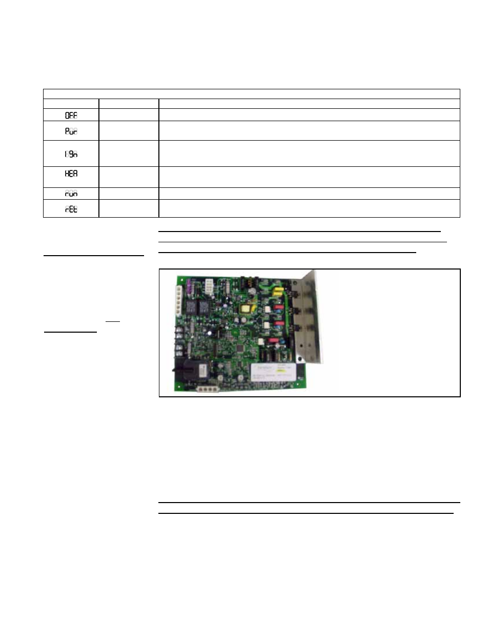
FIGURE 43A - Control
Module used in
Modulating Gas Control
Option AG70 - "D"
Cabinet only
-
1 GREEN FLASH: Stand-by mode. Ready to accept call for heating.
-
1 AMBER FLASH: Heating cycle initiated; gas OFF.
-
2 AMBER FLASH: Heating cycle initiated, all safety checks passed and
gas ON.
-
5 AMBER FLASHES: Suppressed firing rate due to low combustion air or
high altitude operation.
-
RAPID GREEN FLASH: Indicates furnace was manually put into the test
mode
as it applies to ALL Heat Sections with one furnace (Sizes 500, 600,
700, 800) AND the First (upstream) furnace of Heat Sections with two
furnaces (Sizes 1000, 1200, 1400, 1600) of "D" Cabinet Models
Ignition Control System as it applies to second furnace of Heat Sections
with two furnaces (Sizes 1000, 1200, 1400, 1600) of "D" Cabinet Models
The downstream furnace in a "D" cabinet with two heat sections is equipped with a
direct spark integrated control module (circuit board). The module monitors the safety
devices and controls the operation of the venter motors and the gas valve between
heat cycles.
Normal Heat Cycle Operating Sequence - Downstream Furnace of "D"
Cabinet Sizes 1000, 1200, 1400, 1600
1) Call for Heat - The heating/cooling system controller calls for heat. The ignition
system circuit board checks to see that the limit switch is closed and the pressure
switch is open.
- REDB Unit Installation Manual RECB Unit Installation Manual RDDC Unit Installation Manual RDCC Unit Installation Manual RDDB Unit Installation Manual RDCB Unit Installation Manual RDC Unit Installation Manual RCC Unit Installation Manual RDB Unit Installation Manual RCB Unit Installation Manual REDC Unit Installation Manual MAPSIV Unit Installation Manual MAPSIII Unit Installation Manual