0 optional equipment, 1 inlet air options, Outside air only dampers, option ar8 or ar2l – Reznor RECC Unit Installation Manual User Manual
Page 53
Form I-MAPSIII&IV, P/N 222917R9, Page 53
Optional Equipment (alphabetically listed) ..................................Where to Look
Air Control Options, Option AR__ ................................................Paragraph 9.1, pages 53-55
Duct Furnace Curb, Model JHUP (Option JH__) ......................Paragraph 5.4.3, pages 23-25
Electric Heat Section (Models RECB/REDB/RECC/REDC) ........Paragraph 9.3, pages 63-64
plus throughout this manual
Energy Recovery, Option ER1 ............. Paragraph 6.1, page 30, plus Form I-MAPSIII&IV-ER
Gas Heat Section (Models RDCB/RDDB/RDCC/RDDC) ...........Paragraph 9.2, pages 55-63
plus throughout this manual
Inlet Air Hood, Option AS16 & AS19 .........Paragraph 6.3, page 32-37, plus Form I-OPT-WH
Power Exhaust, Option PE .................................................................Paragraph 6.2, page 31
Roof Curbs, Options CJ3, CJ31, CJ34,
CJ49, CJ50, CJ53, CJ54 ........................ Paragraph 5.4, pages 10-28, plus Form I-OPT-C
9.0 Optional
Equipment
including Heat
Sections
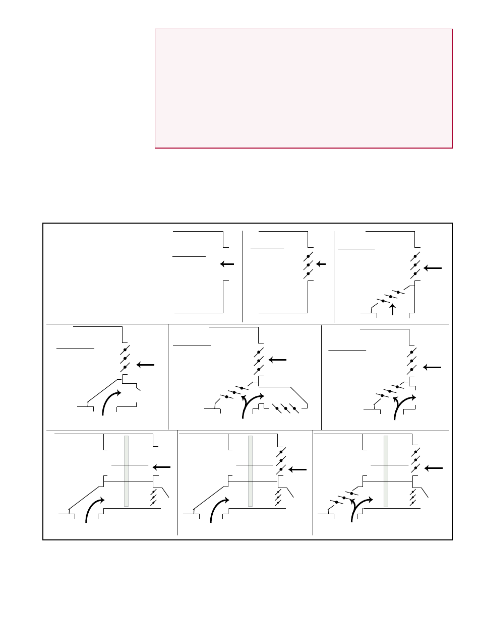
The system may be equipped with a variety of configurations and air control options
including 100% outside air, outside and return air, a variety of damper controls, and the
field-installed energy recovery module in Paragraph 6.1. Inlet air configurations with
and without dampers are identified as Option AR and may apply to the MAPS
®
unit
only or to a MAPS
®
unit with an energy recovery module. Some inlet air options require
additional Option GF controls. Option AR2D is for use with Option PE power exhaust.
Refer to the
FIGURE 34 to identify the appearance of each inlet air configuration.
9.1 Inlet Air Options
Option AR1 -
100% Outside
Air - Cabinet
A, B, C, or D)
(no factory-
installed
dampers)
Option AR8 -
100% Outside Air
with Motorized
Damper for
Cabinet A, B,
C, or D -
damper opening
interlocked with
blower start
Option AR25 - Outside
Air and Return Air with
Motorized Dampers for
Cabinet A, B, C, or D -
requires factory
or field-installed
control
(Option GF)
Outside
Air
Return Air
Option AR2D - 100%
Outside Air with
Motorized Damper
for Cabinet A, B,
or C with power
exhaust
(Option PE)
Exhaust Air
Outside
Air
(Option PE)
(MAPS unit)
(MAPS unit)
(MAPS unit)
(MAPS unit)
Option AR2G - Outside
Air and Return Air with
Motorized Dampers for
Cabinet A, B, or C
with gravity exhaust
damper and hood -
requires factory
or field-
installed
control
(Option GF)
Outside Air
Return /
Exhaust Air
Gravity
Exhaust
(MAPS unit)
Outside
Air
(MAPS unit)
Option AR2J
on Energy
Recovery
Module
(Option ER1)
Cabinet
A, B, or C
with Option
ER1
Exhaust Air
(Energy
Recovery
Module)
Outside
Air
(MAPS unit)
Option AR2L
on Energy
Recovery
Module
(Option ER1)
Cabinet A, B, or C
with Option ER1
Cabinet A, B, or C
with Option ER1
Exhaust Air
(Energy
Recovery
Module)
Outside
Air
(MAPS unit)
Option AR2K
on Energy
Recovery
Module
(Option ER1)
(Energy
Recovery
Module)
Return /
Exhaust Air
Outside
Air
(MAPS unit)
Option AR2H - Outside
Air and Return Air with
Motorized Dampers for
Cabinet A, B, or C
with gravity exhaust -
requires factory
or field-
installed
control
(Option GF)
Return /
Exhaust Air
Gravity
Exhaust
Damper
Gravity
Exhaust
Damper
Gravity
Exhaust
Damper
100% Outside Air
with Motorized
Damper in ER
module interlocked
with unit blower
start
Outside Air &
Return Air with
interlocked Motor-
ized Dampers -
requires control
Option GF2
or GF7
FIGURE 34 -
Inlet Air
Configurations
by AR Option
Inlet Air Dampers and
Controls
Outside Air Only Dampers, Option AR8 or AR2L
-The damper motor is
electrically interlocked with the blower (supply fan) motor such that a command to start
the fan opens the damper first and then allows the fan to run. When the fan is called to
be OFF, the damper closes.
- REDB Unit Installation Manual RECB Unit Installation Manual RDDC Unit Installation Manual RDCC Unit Installation Manual RDDB Unit Installation Manual RDCB Unit Installation Manual RDC Unit Installation Manual RCC Unit Installation Manual RDB Unit Installation Manual RCB Unit Installation Manual REDC Unit Installation Manual MAPSIV Unit Installation Manual MAPSIII Unit Installation Manual