6 blowers, belts, and drives – Reznor RECC Unit Installation Manual User Manual
Page 39
Form I-MAPSIII&IV, P/N 222917R9, Page 39
Improper trap design accounts for some condensate drainage system failures, but
incorrect use and maintenance of condensate drain trap can also cause problems. The
combination of airborne particles and moisture in the air handler can result in algae
formation in the drain pan and trap. The trap must be cleaned regularly to avoid block-
age that can slow or stop water flow, resulting in backup into the system.
If drain has a cleanout opening (
FIGURE 19B), be sure to close the opening after
cleaning.
Seasonal Usage - At the beginning of the cooling season, inspect and clean the entire
cooling coil cabinet including the condensate drain pan. Thoroughly clean dirt, algae,
grease, and other contaminants. Inspect condensate drain pan, trap, and piping; fill
trap with water to ensure proper operation. During a wintertime shutdown of the cool-
ing system, it may be desirable to disconnect and remove all water from the trap and
drain to prevent freeze damage. If local building codes permit, trap may be filled with
an antifreeze solution. Or, piping may be designed with freeze plugs or other freeze
protection methods (such as a heat tape).
Year Round Usage - Climates or applications with cooling requirements year round
require more frequent inspections of the cooling coil cabinet and condensate drains.
Depending on climate, freeze protection of the trap may be required during non-cool-
ing days.
Condensate Drain Use
6.6 Blowers, Belts,
and Drives
6.6.1 Belts and Belt Tension
Blower systems with 1/2 to 5HP motors are equipped with either Power Twist Plus
linked blower belts or solid belts. The linked belts are designed in sections allowing
for easy sizing and adjustment. Blower systems with 7-1/2 or 10 HP motors have
solid V-belts. The belt is sized at the factory for
the proper tension. Check belt tension. Proper belt
tension is important to the long life of the belt and
motor. A loose belt will cause wear and slippage.
Too much tension will cause excessive motor and
blower bearing wear.
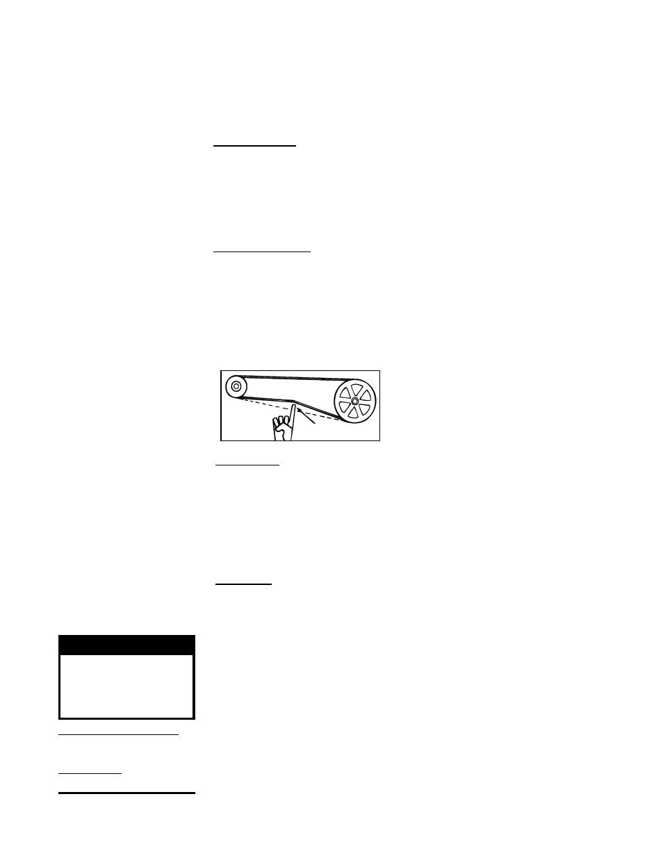
3/4 (19mm)
FIGURE 20 - Belt
Tension
Linked Belts - If the belt needs tightening, the recommended method of tightening the
belt length is to count the number of links and remove one link for every 24. (A link is made
up of two joining sections of belt. For easier removal of links, turn the belt inside out. But be
sure to turn it back before installing. If belt is removed or replaced, be sure to align direc-
tional arrows on the belt to the proper drive rotation.) The belt tension should be checked
after the first 24 hours of running at full load and at regular maintenance inspections.
(
NOTE: After "24-hour run" tension adjustment, required maintenance adjustment may
be by removing links or turning the adjusting screw on the motor base as required to
achieve proper tension. Replace worn links or belts.)
Solid Belts - Adjust the belt tension by turning the adjusting screw on the motor base
until the belt can be depressed 3/4" (19mm). (See
FIGURE 20.) After correct tension
is achieved, re-tighten the locknut on the adjustment screw. Be sure that the belt is
aligned in the pulleys.
6.6.2 Adjusting Blower Speed
The blower speed may be adjusted to achieve the desired air volume, as long as the
adjustment is within the temperature rise and the static pressure limits shown on the
rating plate for both heating and cooling. Motors are factory set between maximum and
minimum blower speeds.
If the duct resistance is low, the blower may deliver too high an air volume. If the resis-
tance is very low, the blower may deliver an excess air volume, which can cause the
overload protector to cycle the motor. Reducing the blower speed will correct these
conditions. If ductwork is added to an installation, it may be necessary to increase the
blower speed.
At final adjustment, amperes should not exceed motor nameplate amp rating. With a
gas heat section, the installation must be adjusted to obtain a temperature rise within
the range specified on the furnace rating plate. Maximum temperature rise for this unit
is 100°F.
NOTE: The information
in Paragraph 6.6 also
applies to an optional power
exhaust blower.
WARNING
All setscrews and
locking collars must
be tightened before
applying power.
Pulley/Shaft Setscrews -
Wrench torque 110 in-lb min-
imum to 130 in-lb maximum.
Bearing Hub - Socket size
5/16"; Torque 165 in-lbs.
- REDB Unit Installation Manual RECB Unit Installation Manual RDDC Unit Installation Manual RDCC Unit Installation Manual RDDB Unit Installation Manual RDCB Unit Installation Manual RDC Unit Installation Manual RCC Unit Installation Manual RDB Unit Installation Manual RCB Unit Installation Manual REDC Unit Installation Manual MAPSIV Unit Installation Manual MAPSIII Unit Installation Manual