Optional equipment (cont'd), Sizing gas supply lines, 2 gas piping and pressures (cont'd) – Reznor RECC Unit Installation Manual User Manual
Page 56
Form I-MAPSIII&IV, Page 56
WARNING
The operating valve is the prime safety shutoff. All gas supply
lines must be free of dirt or scale before connecting the unit to
ensure positive closure.
9. Optional
Equipment
(cont'd)
WARNING
All components of a gas supply system must be leak tested prior to placing equipment in
service. NEVER TEST FOR LEAKS WITH AN OPEN FLAME. Failure to comply could result
in personal injury, property damage or death.
Sizing Gas Supply
Lines
Capacity of Piping
Cubic Feet per Hour based on 0.3" w.c. Pressure Drop
Specific Gravity for Natural Gas -- 0.6 (Natural Gas -- 1000 BTU/Cubic Ft)
Specific Gravity for Propane Gas -- 1.6 (Propane Gas -- 2550 BTU/Cubic Ft)
Length
Diameter of Pipe
of
1/2"
3/4"
1"
1-1/4"
1-1/2"
2"
Pipe
Natural Propane Natural Propane Natural Propane Natural Propane Natural Propane Natural Propane
20'
92
56
190
116
350
214
730
445
1100
671
2100
1281
30'
73
45
152
93
285
174
590
360
890
543
1650
1007
40'
63
38
130
79
245
149
500
305
760
464
1450
885
50'
56
34
115
70
215
131
440
268
670
409
1270
775
60'
50
31
105
64
195
119
400
244
610
372
1105
674
70'
46
28
96
59
180
110
370
226
560
342
1050
641
80'
43
26
90
55
170
104
350
214
530
323
990
604
90'
40
24
84
51
160
98
320
195
490
299
930
567
100'
38
23
79
48
150
92
305
186
460
281
870
531
125'
34
21
72
44
130
79
275
168
410
250
780
476
150'
31
19
64
39
120
73
250
153
380
232
710
433
175'
28
17
59
36
110
67
225
137
350
214
650
397
200'
26
16
55
34
100
61
210
128
320
195
610
372
Note: When sizing supply lines, consider possibilities of future expansion and increased requirements.
Refer to National Fuel Gas Code for additional information on line sizing.
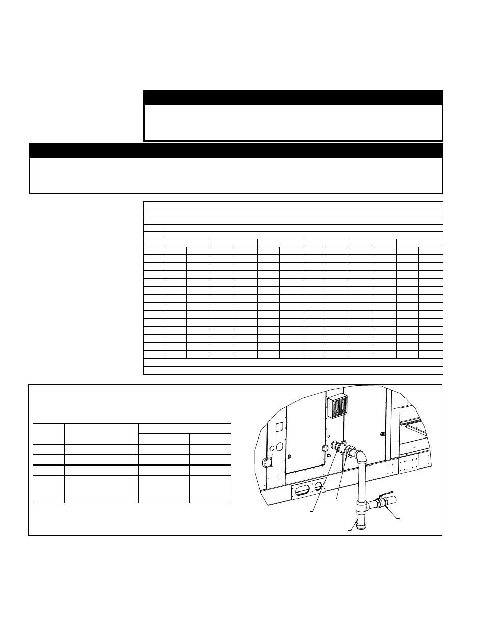
Cabinet
Size
Heat Section
Gas Connection
Natural Gas
Propane
A
100, 150, 200
1/2”
1/2”
B
250, 300
3/4”
3/4”
C
400, 500, 600, 700
1”
--
D
500, 600, 700, 800,
100, 1200, 1400,
1600
1”
--
Manual
Valve
Drip Leg
Union
Reduce supply line.
Gas connection
is 1” npt.
FIGURE 37 - Gas Connection
(D Cabinet illustrated)
Supply Pressures
Before attempting to measure valve outlet and manifold gas pressure, the inlet supply
pressure must be within the specified range both when the heater is in operation and
on standby. Incorrect inlet pressure could cause excessive valve outlet gas pressure
immediately or at some future time.
Natural gas inlet supply pressure for all gas control systems must be a minimum of 6.0"
w.c. Maximum natural gas supply pressure is 14" w.c.
Furnaces for natural gas are orificed for operating with gas having a heating value of
1000 (±50) BTU per cubic ft. If the gas at the installation does not meet this specifica-
tion, consult the factory for proper orifice.
Pipe joint compounds (pipe dope) shall be resistant to the action of liquefied petroleum
gas or any other chemical constituents of the gas being supplied.
9.2 Gas Heat -
Models RDCB,
RDDB, RDCC,
RDDC (cont'd)
9.2.1.2 Gas Piping and Pressures (cont'd)
- REDB Unit Installation Manual RECB Unit Installation Manual RDDC Unit Installation Manual RDCC Unit Installation Manual RDDB Unit Installation Manual RDCB Unit Installation Manual RDC Unit Installation Manual RCC Unit Installation Manual RDB Unit Installation Manual RCB Unit Installation Manual REDC Unit Installation Manual MAPSIV Unit Installation Manual MAPSIII Unit Installation Manual