0 mounting (cont'd), 4 mounting on a roof curb (cont'd), Roof curbs for maps – Reznor RECC Unit Installation Manual User Manual
Page 26: Iii cabinet size d roof curb, Iii cabinet d
Form I-MAPSIII&IV, Page 26
CAUTION: Before installation, recheck to be sure that the correct curb
has been ordered. Be sure that the curb selected matches the unit
ordered. Verify the dimensions of the curb received with the dimension
table. Roof curb installation is the responsibility of the installer.
Assembly and
Installation Instructions
for MAPS
®
III Cabinet
Size D Roof Curb
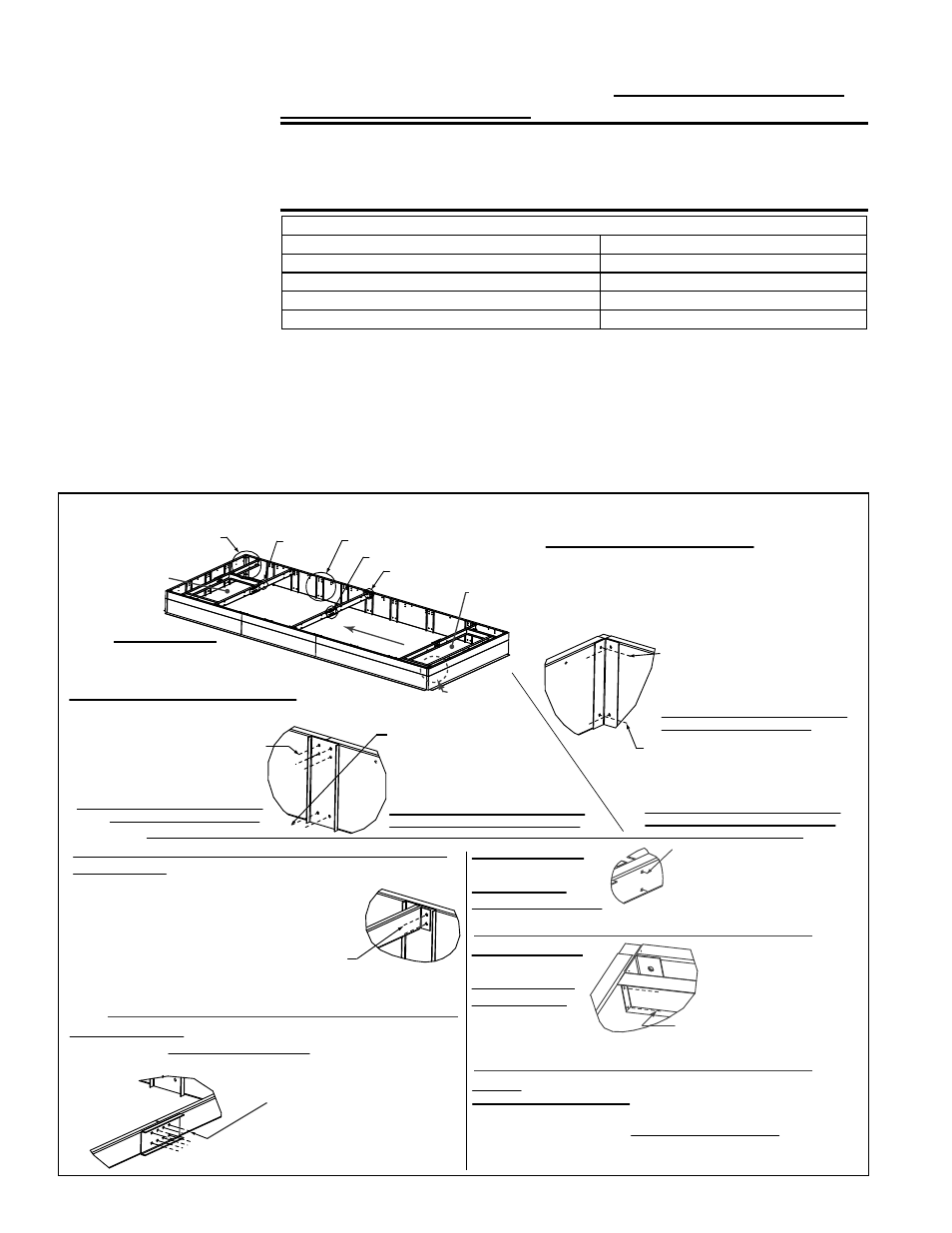
1. Curb Rails - Position the roof curb rails as shown in FIGURES 12A and 12D.
When installing a curb for a unit with heat section size 1000, 1200, 1400 or 1600,
be sure to
place the longer curb side pieces at the return air end. Assemble
the corners and sides as shown in STEPS 1 and 2 in
FIGURE 12B.
2. Cross Supports - Position the four two-piece roof curb cross supports and splice
brackets in the locations shown in
FIGURE 12D. Be certain to turn supports so
that the splice brackets will not be in the duct openings. Assemble as shown
in STEPS 3 and 4 in
FIGURE 12B.
Note: If the installation
has horizontal inlet only
or horizontal discharge,
it is not necessary
to install the unused
duct supports.
Cross
supports must always
be installed.
Assembly Hardware and Tape shipped with curb:
(24)
P/N 163334, Cap Screw, 7/16-14 x 2-1/2" long
(16)
P/N 7328, Hex Nut 1/4-20 Keps
(40)
P/N 163335, Cap Screw, 7/16-14 x 3/4" long
(4)
P/N 114485 1/4-28 x 2-1/2 Bolt
(64)
P/N 15119, Lockwasher, 7/16-14
(4)
P/N 114486, Hex Nut 1/4-28
(64)
P/N 15117, Hex Nut, 7/16-14
(4)
P/N 96854, 1/4" Ext Tooth Lockwasher
(16)
P/N 47252, 1/4-20 x 5/8 Bolt
66302 1-1/4 x 1/4 x 50 ft Sealant Tape
STEP 1 - Detail A - Curb Corner
Position rails as illustrated. If installing Pkg
P/N 220342, be sure to put the two longer
rail side pieces at the return air end.
Position the angle support in the corner and
attach with hardware as illustrated.
Hardware used for 4 Corner Tops:
(8) 2-1/2” Cap Screws, P/N 163334
(8) Lock Washers, P/N 15119
(8) Hex Nuts, P/N 15117
TOP - Cap screw heads should be
on the wood side of the rail.
Hardware used for 4 Corner Bottoms:
(8) 3/4” Cap Screws, P/N 163335
(8) Lock Washers, P/N 15119
(8) Hex Nuts, P/N 15117
BOTTOM - Cap screw heads should
be on the insulation side of the rail.
STEP 2 - Detail B - Rail Side Seam
Connect rail side pieces with the support channels
and hardware as illustrated.
Hardware used for 4 Seams (Top):
(16) 2-1/2” Cap Screws, P/N 163334
(16) Lock Washers, P/N 15119
(16) Hex Nuts, P/N 15117
TOP - Cap screw heads should be
on the wood side of the rail.
Hardware used for
4 Seams (Bottom):
(8) 3/4” Cap Screws, P/N 163335
(8) Lock Washers, P/N 15119
(8) Hex Nuts, P/N 15117
BOTTOM - Cap screw heads should
be on the insulation side of the rail.
STEP 3 - Detail C - Attaching 8 Cross Support Pieces to
the Side Rails (See FIGURE 12D for locations.)
Determine locations of the four cross supports;
dimensions are in FIGURE 12D.
Follow the instructions to attach the ends of all 8
center cross support pieces (4 cross supports;
each with two pieces)
1) Remove the two screws at the
top of the curb rail.
STEP 4 - Detail D - Attaching Splicing Bracket to Connect
Centers of the Four Cross Supports (NOTE: If splice is in a
duct opening, bracket MUST NOT BE INSIDE the opening.)
Hardware for attaching the four
Splicing Brackets:
(32) 3/4” Cap Screws, P/N 163335
(32) Lock Washers, P/N 15119
(32) Hex Nuts, P/N 15117
Curb Assembly
See Dimensions in
FIGURE 12D.
See Detail A
See
Detail E
See Detail B
See Detail D
See Detail C
STEP 5 - Detail E -
Attaching the Two
Discharge Air
Duct Side Supports
to Curb Cross Supports
See FIGURE 12D; position and
attach the two discharge duct
side supports “inside” the curb
cross supports.
(8) 1/4-20 x 5/8 Bolts, P/N 47252
(8) 1/4-20 Hex Nuts, P/N 7328
Discharge
Duct Opening
Return Air
Opening
STEP 6 - Detail F -
Attaching Two
Return Air Duct
Side Supports
to Curb Rail
(one end of
each support)
See Detail F
(4) 1/4-28 x 2-1/2 Bolt, P/N 114485
(4) Hex Nut 1/4-28, P/N 114486
(4) Lock Washers, P/N 96854
STEP 7
- Repeat Detail E (STEP 5) to attach the opposite ends of the
return air duct side supports (attached in STEP 6) to the cross support.
Repeat Detail E (STEP 5) again to complete the return air duct support
by attaching each end of the return air duct end support to the installed
side supports.
(8) 1/4-20 x 5/8 Bolts, P/N 47252; (8) 1/4-20 Hex Nuts, P/N 7328
2) Position the cross support at the top of the curb as illustrated.
3) Re-insert screws attaching the cross support.
Unit Airflow
FIGURE 12B - Option CJ3 Roof Curb Assembly for MAPS
®
III Cabinet D
5.0 Mounting
(cont'd)
5.4.4.Roof Curbs for MAPS
®
III
Models RCB, RDB, RDCB, RDDB,
RECB, REDB Cabinet Size D (cont'd)
5.4 Mounting on a Roof Curb (cont'd)
- REDB Unit Installation Manual RECB Unit Installation Manual RDDC Unit Installation Manual RDCC Unit Installation Manual RDDB Unit Installation Manual RDCB Unit Installation Manual RDC Unit Installation Manual RCC Unit Installation Manual RDB Unit Installation Manual RCB Unit Installation Manual REDC Unit Installation Manual MAPSIV Unit Installation Manual MAPSIII Unit Installation Manual