4 duct connections and ductwork – Reznor RECC Unit Installation Manual User Manual
Page 37
Form I-MAPSIII&IV, P/N 222917R9, Page 37
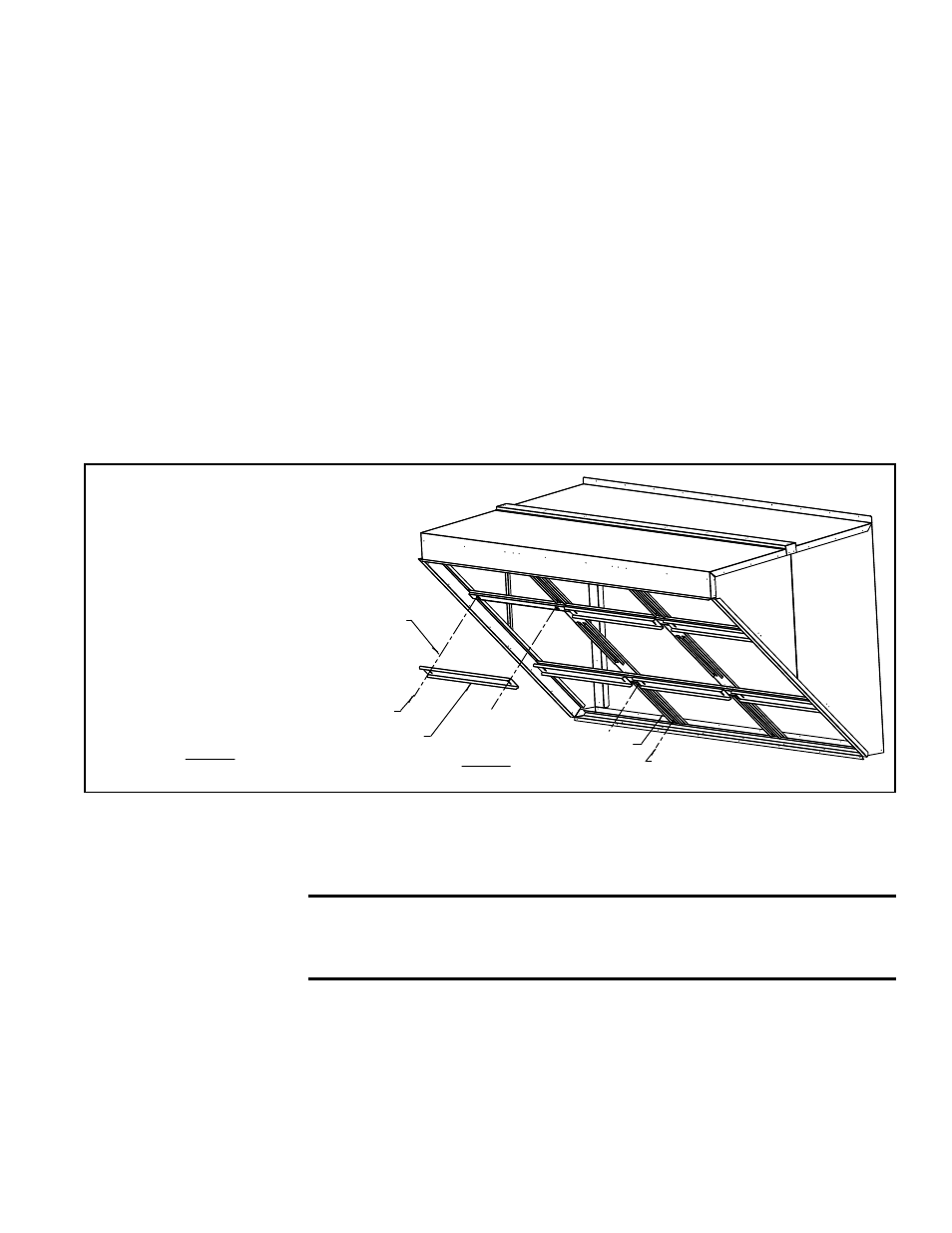
(12) Nylon Retainers,
P/N 205709
(12) Wing Head Screws,
P/N 205707
(6) Filter Retainers, P/N 222706
STEP 4b) - Install filters. Attach retainers
with wing head screws and nylon retainers.
(12) Filter Stops, P/N 222705
STEP 4a) - Attach filter stops.
Attach stops with
sheetmetal screws.
FIGURE 18E -
STEP 4, Install Stops,
Filters, and Retainers
c) Install Side Gutters - Position the left side gutter on the left side of the cabinet.
Line up the holes and attach with sheetmetal screws. Repeat with the right side
gutter.
d) Install Two Vertical Filter Supports - Position a vertical support as illustrated so
that it is lined up with two holes in the top edge and two in the bottom. Attach with
sheetmetal screws. Repeat with the second support.
e) Install Two Horizontal Filter Supports - Position a horizontal support as illus-
trated so that it is lined up with two holes on each side. Attach to the sides and the
gutters with sheetmetal screws. Where the horizontal support crosses the vertical
supports, attach with sheetmetal screws. Repeat with the second horizontal filter
support.
4. Install Filter Stops, Filters (not illustrated here; see FIGURE 18A), and Filter
Retainers (FIGURE 18E)
a) Install 12 Filter Stops - Position the filter stops on the vertical supports. Attach
filter stops with sheetmetal screws but do not tighten.
b) Install the 18 Filters and six Filter Retainers - Starting with either the bottom or
the top row, position two filters in an opening, adjust stop, remove filters, tighten
stop, and return filters to position. Holding filters in place, use nylon retainers, wing
head screws, and the clip-on retainers installed in
STEP 3E to secure the filter
retainer. Install the other filters in that row. Install the other two rows of filters and
their retainers.
NOTE: If installing MAPS
®
unit with electric heat
(Model RECB, REDB,
RECC, or REDC), see
Paragraph 8.1.1 about
placement of discharge air
sensor.
6.4 Duct
Connections
and Ductwork
Requirements and Suggestions for Installing Ducts
Duct connections for MAPS
®
units are in the roof curb designed for the unit, See Para-
graph 5.4 for duct connection sizes. Downflow roof curbs are designed for installing
ductwork from the top before setting the unit on the curb.
CAUTION: An external duct system static pressure not within
the limits shown on the rating plate, or improper motor pulley
or belt adjustment, may overload the motor.
• Type of Ductwork - The type of duct installation to be used depends in part on
the construction of the roof (whether wood joist, steelbar joist, steel truss, pre-cast
concrete) and the ceiling (whether hung, flush, etc.).
• Ductwork Material - Rectangular duct should be constructed of not lighter than
No. 26 U.S. gauge galvanized iron or No. 24 B & S gauge aluminum.
• Ductwork Structure - All duct sections 24 inches (610mm) or wider, and over 48
inches (1219mm) in length, should be cross broken on top and bottom and should
have standing seams or angle-iron braces. Joints should be S and drive strip, or
locked.
- REDB Unit Installation Manual RECB Unit Installation Manual RDDC Unit Installation Manual RDCC Unit Installation Manual RDDB Unit Installation Manual RDCB Unit Installation Manual RDC Unit Installation Manual RCC Unit Installation Manual RDB Unit Installation Manual RCB Unit Installation Manual REDC Unit Installation Manual MAPSIV Unit Installation Manual MAPSIII Unit Installation Manual