5 condensate drains, 0 mechanical (cont'd), Ba a/2 – Reznor RECC Unit Installation Manual User Manual
Page 38: Lunit, 4 duct connections and ductwork (cont'd)
Form I-MAPSIII&IV, Page 38
All systems require a condensate drain on the cooling section and all "D" cabinet mod-
els with gas heat require a drain on the heat section.
ALL Models - A slide-out, removable drain pan with a 1 or 1-1/2" male NPT
condensate drain connection is located below the coil cabinet. When connecting
the drain line, provide a means of disconnecting the line at or near the cabinet
connection to allow the drain pan to be removed for cleaning.
D Cabinet Models RDDB and RDCB - Below the gas heat section that is closest
to the blower, there is 1/2" male NPT connection for a condensate drain line.
Follow the instructions below to install a trap in each drain.
Do not reduce the drain
diameter. Pitch the drain line at least 1/2" (13mm) for every 10 feet (3M) of horizontal
run. Drain lines must not interfere with drain pan or access panels.
An obstruction in the drain or a poorly designed drain can cause the condensate pan to
over flow. Overflow could result in damage to the unit and/or the building.
If the installation or local code requires, run drain into a waste water system.
6.5 Condensate
Drains
NOTE: Do not reduce
the diameter of the
condensate drain
piping.
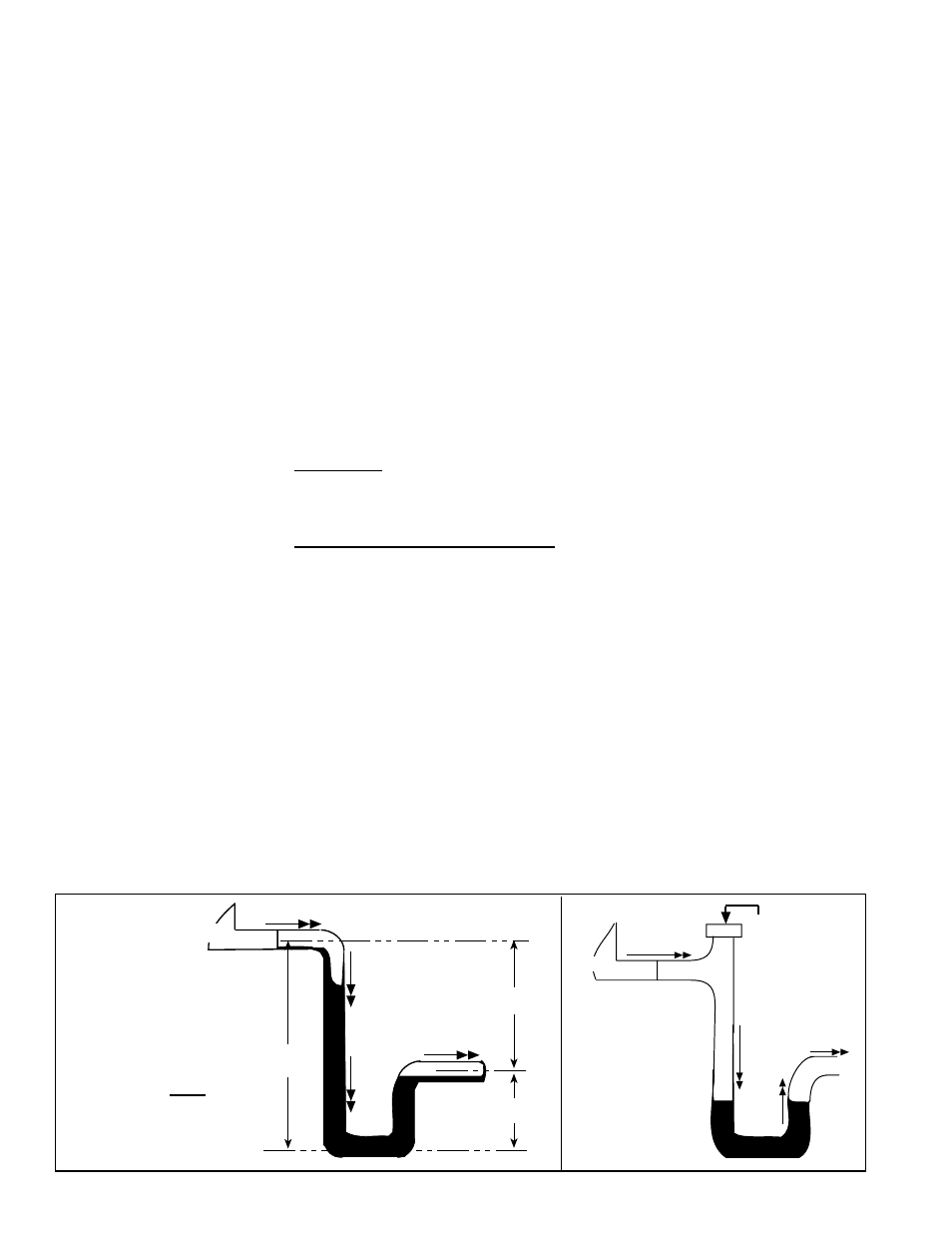
The design of the drain trap is important. Since the condensate drain pan is on the
blower inlet side, there is a negative pressure at the drain relative to the ambient. The
trap height must account for this static pressure difference. Maximum negative static
can be determined by reading the negative pressure at the blower inlet and adding .2”
w.c. to allow for dirty filters.
If dimension "B" in
FIGURE 19A is not tall enough, the water seal will not hold, and air
will be drawn through the drain pipe into the system. If the outlet leg of the trap is too
tall, water will back up into the drain pan. As condensate forms during normal opera-
tion, the water level in the trap rises until there is a constant outflow.
FIGURE 19A
illustrates the appropriate dimensions for trapping a negative pressure system.
Condensate Drain Trap
6.0 Mechanical
(cont'd)
To prevent air
from entering
always close
the cleanout.
Water Flow
Unit
FIGURE 19B -
Drain Trap with
Cleanout
B
A
A/2
C
L
C
L
C
L
Unit
Water Flow
Water Flow
A = 1" (25mm) for
each 1" (25mm) of
maximum static
pressure plus 1"
(25mm)
B = A + A/2
FIGURE 19A -
Condensate
Drain Trap
Dimensions
• Through Masonry Walls - No supply air duct should come in contact with
masonry walls. Insulate around all air ducts through masonry walls with not less
than 1/2" (13mm) of insulation. 1" (25mm) is recommended.
• Through Uncooled/Unheated Space - Insulate all exposed supply air ducts
passing through an uncooled or unheated space with at least 1/2" (1" is
recommended) of insulation.
• Duct Supports - Suspend all ducts securely from buildings members. Do not
support ducts solely by the unit duct connections.
• Duct Sizing - Proper sizing of the supply air ductwork is necessary to ensure a
satisfactory installation. The recognized authority for such information is the Air
Conditioning Contractors Association, 2800 Shirlington Road, Suite 300, Arlington,
VA 22206 (www.acca.org). A manual covering duct sizing in detail may be
purchased directly from them.
• Duct Connections - To minimize sound and vibration transmission, use
flexible duct connections. Ducts must be attached and sealed to provide airtight
connections.
• Return Air Duct/Grill Size - Make certain that return air ducting or grill has a free
area equal to the return duct size connection.
6.4 Duct
Connections
and Ductwork
(cont'd)
- REDB Unit Installation Manual RECB Unit Installation Manual RDDC Unit Installation Manual RDCC Unit Installation Manual RDDB Unit Installation Manual RDCB Unit Installation Manual RDC Unit Installation Manual RCC Unit Installation Manual RDB Unit Installation Manual RCB Unit Installation Manual REDC Unit Installation Manual MAPSIV Unit Installation Manual MAPSIII Unit Installation Manual