2 dimensions, 1 dimensions - cabinet sizes a, b, and c – Reznor RECC Unit Installation Manual User Manual
Page 7
Form I-MAPSIII&IV, P/N 222917R9, Page 7
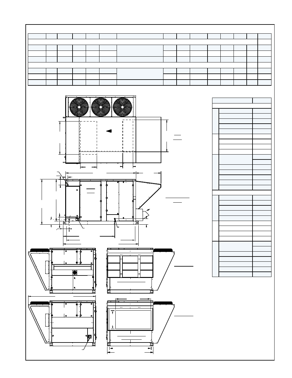
FIGURE 3A - General Arrangement and Dimensions (inches/mm) - Cabinets A, B, and C
4.2 Dimensions
Cabinet A
B
C
D
E
F
G
H
J
K
L
M*
N*
P*
Dimensions - inches
A
84
73-7/8
49
43-7/8 76-1/4
26-3/4 (Opt AS16);
44 (Opt AS19)*
41-7/8 39-1/2 72-5/8 24-1/4 20-1/4 12-1/2 27 17-1/2
B
84
73-7/8
49
43-7/8 76-1/4
56-7/8 54-1/2 87-5/16 36-1/4 20-1/4 12-1/2 39 17-1/2
C
113 102-1/2 67-3/4 62-5/8 105-3/16 37-5/8 (Opt AS16&AS19)
68-1/2
66
101-3/16 49-7/8 25-7/8 15-1/2 48 24-3/4
Dimensions - mm
A
2134 1870
1245 1114
1937
679 (Opt AS16);
1118 (Opt AS19)*
1064 1003
1837
616
514
318
686
445
B
2134 1870
1245 1114
1937
1445 1384
2218
921
514
318
991
445
C
2870 2604
1721 1591
2672
986 (Opt AS16&AS19)
1740 1677
2570
1267
657
394 1219 629
*Outside air hood Option AS19 is required with power exhaust or energy recovery module option.
Cabinet & Heat Size
Q*
Dimensions - inches
A
No Heat
26-1/2
Electric Heat
26-1/2
100 MBH (gas)
19
150 MBH (gas)
26-1/2
200 MBH (gas)
34
B
No Heat
49
Electric Heat
49
250 MBH (gas)
41-1/2
300 MBH (gas)
49
C
No Heat
32-5/8**
49-5/8***
Electric Heat
49-5/8
400 MBH (gas)
32-5/8
500 MBH (gas)
44-5/8
600 MBH (gas)
49-5/8
700 MBH (gas)
54-5/8
Dimensions - mm
A
No Heat
673
Electric Heat
673
100 MBH (gas)
483
150 MBH (gas)
673
200 MBH (gas)
864
B
No Heat
1245
Electric Heat
1245
250 MBH (gas)
1054
300 MBH (gas)
1245
C
No Heat
829**
1260***
Electric Heat
1260
400 MBH (gas)
829
500 MBH (gas)
1133
600 MBH (gas)
1260
700 MBH (gas)
1387
4.2.1 Dimensions - Cabinet Sizes A, B, and C
Bottom
Supply
Air
Opening
Bottom Return Air Opening
Airflow
Outside
Air Hood
Outside
Air Hood
Power Inlet
2” (51mm) ø
8-3/16 (208)
Control
Panel
Coil
Access
Front
View
8-3/4 (222)
3-3/16 (81)
Motor and
Blower
Access
Filter and Reheat
Compressor Access
Drain
1” NPT
Control Voltage
Inlet
11
(279)
77-1/2 (1969)
Tubing
Access
Compressor
Access
High
Voltage
Electrical
Gas Heat
Section
Inlet Air End View
(with hood installed;
optional exhaust not shown)
Condenser
Section
Q
P
Optional Power Exhaust
(See dimensions,
Paragraph 6.2.)
E
F
8-1/16
(205)
C
D
A
(length of base)
B
(inside of curb cap)
Tubing
Access
Compressor
Access
High
Voltage
Electrical
Electric Heat
Section
Disconnect Switch
Inlet Air End View
(without hood)
Condenser
Section
G
(width of base)
H
(inside curb cap)
Top
View
Control Side
View
End Views -
Models with
Gas Heat
Section
End Views -
Models with
Electric Heat
Section
Combustion Air Intake Panel
Vent
(NOTE: Two sets of End
Views shown for appearance.
Dimensions shown in End
Views apply to all Models.)
End of Base to
Gas Connection
Sizes A&B 8-1/4 (210)
Size C 9-3/8 (238)
K
M
N
L
Gas
J
NOTES:
*M, N, P, & Q are opening sizes
in the bottom of the cabinet. Duct
flanges are in the roof curb; see
Form I-OPT-C for duct connection
dimensions.
**Applies to Model RCB 190, 216;
RCC 190; RDB 248, 262, 272,
288; RDC 248, 262
*** Applies to Models RCB & RCC
298, 410; RDB & RDC 354, 370,
468, 482
For cross-reference of cabinet
size to model size, see
APPENDIX, pages 71-72.
- REDB Unit Installation Manual RECB Unit Installation Manual RDDC Unit Installation Manual RDCC Unit Installation Manual RDDB Unit Installation Manual RDCB Unit Installation Manual RDC Unit Installation Manual RCC Unit Installation Manual RDB Unit Installation Manual RCB Unit Installation Manual REDC Unit Installation Manual MAPSIV Unit Installation Manual MAPSIII Unit Installation Manual