0 controls (cont'd) – Reznor RECC Unit Installation Manual User Manual
Page 48
Form I-MAPSIII&IV, Page 48
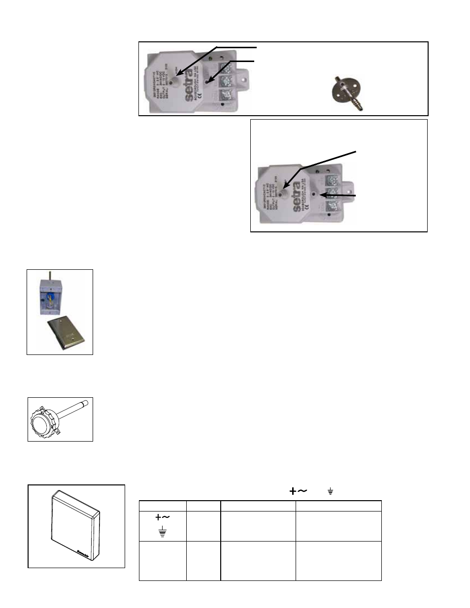
FIGURE 28A -
Tubing Ports on the
Transducer in Option
BE11 and Ductwork
Sensor Port
High Pressure Port - Attach tubing.
Low Pressure Port -
Leave open.
or attach
tubing.
High Pressure
Data Sensor
Port - Attach to
ductwork. Slide
tubing on barb.
Option BE12, Building Static Pressure Sensor
The differential pressure transducer (
P/N 234819) used in
Option BE12 is mounted in the low voltage compartment. The
transducer has a high and a low tubing port. Depending on the
application, attach tubing to both ports or leave one open to
atmospheric pressure. Connect 1/4" field-supplied tubing to the
port(s) and run it to the pressure reference point(s). Cut the end
of the tubing at a 45° angle to minimize the affect of air move-
ment and attach it to a wall or in a ceiling. The transducer has
a range of -0.5 to .5" w.c. and was calibrated at the factory; it
should not need field adjustment. Refer to the manufacturer's
instructions in the owner's envelope for additional information.
High Pressure
Port - Connect to
the high pressure
reference point.
Low Pressure
Port - Connect to
the low pressure
reference point.
FIGURE 28B - Tubing Ports on Option
BE12, Building Static Pressure Sensor
8.1 Cooling/ Dehumidification/Heating Control (cont'd)
8.0 Controls
(cont'd)
Option BE13, Return Air Temperature Sensor
The return air temperature sensor (
P/N 222753) is shipped loose for field installation
in the return air ductwork. The position of the sensor is important. In a horizontal return
air ductwork, locate the sensor assembly in the top, middle of the duct with the sensor
probe extending vertically down into the center of the airstream. In vertical return air
ductwork, locate the sensor assembly in the middle of the side of the duct that corre-
sponds with the middle of the discharge outlet.
Mark the location and drill a 7/16" hole. Insert the probe in the hole. With the probe
centered in the hole, attach with two #8 sheetmetal screws. Be sure the hole is sealed.
Refer to Paragraph 8.1.1 and follow the same guidelines for the sensor wire. Wires
will attach to the sensor and to the controller expansion board. Refer to the unit wiring
diagram.
Option BE14, Return Air Humidity Sensor
The return air humidity sensor (
P/N 234907) is shipped loose for field installation in the
return air ductwork. The sensor must be located away from areas of excessive mois-
ture, corrosive fumes, vibration, or extremely high temperature.
To install, mark the selected location and drill a 3/4" hole. Insert the stainless steel
probe into the hole until the foam is in direct contact with the duct. Attach the RH trans-
mitter using two #8 x 3/4" self-tapping screws.
Follow the requirements in Paragraph 8.1.1 to run the sensor wire. To connect the wire
to the sensor, remove the cover and install conduit connectors.
Wires will connect to the controller expansion board. Refer to the unit wiring diagram.
FIGURE 28C - Return
Air Temperature
Sensor, P/N 222753
Option BE15, Building CO
2
Sensor
The sensor (
P/N 234820) used in Option BE15 must be field mounted in the building
and electrically connected to the I/Q controller expansion board (Option BHB6). Follow
the manufacturer's instructions to mount the sensor. Connect the wires as instructed
below. Power supply must be connected to
and
FIGURE 28D -
Return Air Humidity
Sensor, P/N 234907
Sensor Terminal
Function
Electrical Data
Remarks / Standard Settings
Power (+)
Power
ground (-)
24 VAC/DC+ (±10%), 2W
24 VAC/DC -
System voltage reference
OUT 1
OUT 2
Analogue
output 1 (+)
Analogue
output 2 (+)
0-10 VDC
2.0-10.0 VDC or 4.0-20.0 mA
0.9 - 1.6 VDC or 1.5-2.5mA
0 VDC or 0 mA
0-2000 ppm CO2
0-2000 ppm CO2
Status = ERROR
Status = NOT READY
FIGURE 28E - CO2
Sensor, P/N 234820
- REDB Unit Installation Manual RECB Unit Installation Manual RDDC Unit Installation Manual RDCC Unit Installation Manual RDDB Unit Installation Manual RDCB Unit Installation Manual RDC Unit Installation Manual RCC Unit Installation Manual RDB Unit Installation Manual RCB Unit Installation Manual REDC Unit Installation Manual MAPSIV Unit Installation Manual MAPSIII Unit Installation Manual