2 gas heat - rdcb, rddb, rdcc, rddc, Sensor and for the control system, 2 gas heat - models rdcb, rddb, rdcc, rddc – Reznor RECC Unit Installation Manual User Manual
Page 55: 1 gas heat module - mechanical
Form I-MAPSIII&IV, P/N 222917R9, Page 55
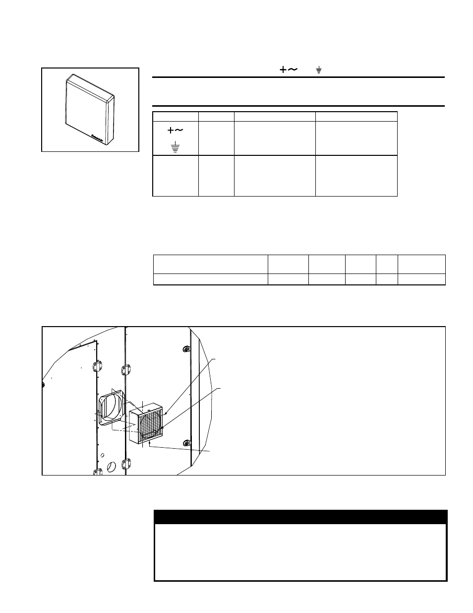
Option GF6, Building CO
2
Sensor
The sensor (
P/N 234820) used in Option GF6 must be field mounted in the building
and electrically connected to the I/Q controller expansion board (Option BHB6). Follow
the manufacturer's instructions to mount the sensor. Connect the wires as instructed.
Power supply must be connected to
and
CAUTION: The same ground reference has to be used for the
CO
2
sensor and for the control system.
FIGURE 35B - CO2
Sensor, P/N 234820
Sensor Terminal
Function
Electrical Data
Remarks /Standard Settings
Power (+)
Power
ground (-)
24 VAC/DC+ (±10%), 2W
24 VAC/DC -
System voltage reference
OUT 1
OUT 2
Analogue
output 1 (+)
Analogue
output 2 (+)
0-10 VDC
2.0-10.0 VDC or 4.0-20.0 mA
0.9 - 1.6 VDC or 1.5-2.5mA
0 VDC or 0 mA
0-2000 ppm CO2
0-2000 ppm CO2
Status = ERROR
Status = NOT READY
9.2 Gas Heat -
Models RDCB,
RDDB, RDCC,
RDDC
A system with a gas heat section is equipped with a Reznor
®
T
CORE
2
®
combustion sys-
tem from 100 to 1,600 MBH input. The 80% thermal efficient furnace is power vented
and has either a staged gas control or depending on size either a 8:1 or 16:1 turndown
modulating gas capacity control.
Temperature Guidelines
for Gas Heat Section
Minimum Circulating Discharge
Air Temperature (°F)
80
75
70
65
60
Minimum Design Ambient (°F)
-30 to - 21 -20 to - 11 -10 to -1 0 to 9 10 and above
9.2.1 Gas Heat
Module - Mechanical
9.2.1.1 Screened Vent Cover - MAPS
®
III "D" Cabinet
The vent cover is shipped with the unit for field installation. Each package includes the
assembled vent cover,
P/N 222614, and four sheetmetal screws, P/N 11813.
FIGURE 36 - Install a Vent Cover on
Each Gas Furnace - D Cabinet Sizes
Vent Cover Assembly,
P/N 222614
(1 for Sizes 500,
600, 700, 800;
2 for Sizes 1000,
1200, 1400, 1600)
Sheetmetal Screws,
P/N 11813 (4 for each
vent box assembly)
Drain hole MUST be
on the bottom.
Instructions
1. Position the cover over the vent
being sure that the drain hole in
the box is toward the bottom.
2. Attach the vent cover with the four
screws as illustrated.
3. On heat sections with two
furnaces (Cabinet D Sizes 1000,
1200, 1400, and 1600), install a
vent cover on each furnace.
9.2.1.2 Gas Piping and
Pressures
All piping must be in accordance with requirements outlined in the National Fuel Gas
Code ANSI/Z223.1a (latest edition) or CSA-B149.1 and B149.2. Gas supply piping
installation should conform with good practice and with local codes.
WARNING: PRESSURE TESTING SUPPLY PIPING
Test pressures ABOVE 1/2 psi (3.5kPa): Disconnect the heater
and the manual valve from the gas supply line which is to be
tested. Cap or plug the supply line. Test pressure EQUAL TO or
BELOW 1/2 psi (3.5kPa): Before testing, close the manual valve
at the heater.
- REDB Unit Installation Manual RECB Unit Installation Manual RDDC Unit Installation Manual RDCC Unit Installation Manual RDDB Unit Installation Manual RDCB Unit Installation Manual RDC Unit Installation Manual RCC Unit Installation Manual RDB Unit Installation Manual RCB Unit Installation Manual REDC Unit Installation Manual MAPSIV Unit Installation Manual MAPSIII Unit Installation Manual