Reznor RECC Unit Installation Manual User Manual
Page 21
Form I-MAPSIII&IV, P/N 222917R9, Page 21
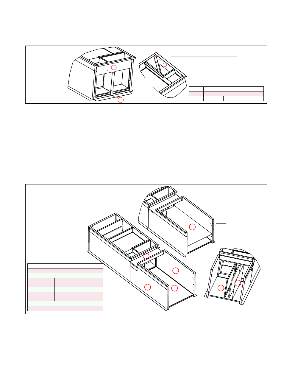
FIGURE 10D -
IInstall Unit Curb
End (
P
) & Liner
Supports (
2 Q's
)
for the curb
section under
the Energy
Recovery
Module
6. Install end connector (
Code
P
) and two liner supports (
Code
Q
) (
FIGURE 10D).
a) Position end connector (
Code
P
) as illustrated. Attach at both corners with
hardware listed. Attach the "front" with sheetmetal screws.
b) Position liner supports (
Code
Q
) in the openings and attach with sheetmetal
screws.
FIGURE 10E - Install
Curb Sides for
supporting ER Module,
Duct Bottom, Tunnel
between the unit curb
and the ER curb, Duct
Liner, and Duct Divider
7. Install energy recovery curb section sides, duct bottom and divider, and "tunnel"
cover.
a) Position curb sides (
Codes R &
S
) and attach to sides (
B & B) with sheetmetal
screws.
b) Position the duct bottom (
Code
T
) in the curb with insulation side up. Align the
holes (push the insulation out of the way) and attach partition to curb sides (
R
& S). Attach the bottom (
Code
T
) to the connector end (
P).
c) Position the bottom liner (
Code
V
). Align the holes and attach with sheetmetal
screws.
d) Position the tunnel (
Code
U
) over the gap between the unit and energy
recovery curb sections. Attach with sheetmetal screws.
e) Position the vertical, insulated duct divider (
Code
W
); attach it to the bottom
liner and the tunnel (
Code
U
). Position the liner (
Code
X
) over the insulation
and attach.
P
Q
P
Inside View
(from top)
M
B
G2
L
3/4” Hex Head Cap Screws
with Lockwashers and
Hex Nuts (8 per corner)
2” Lag Screw and
Lockwasher (2 per corner)
Corner Hardware for attaching “P”:
M
N
B
A
B
C
F
M
G2
G1
N
U
R
S
T
(insulation
up)
V
Liner
R
S
U
B
W
X
S
R
V
NOTE: Cabinet B - Insulated
duct bottom (
T
) is two-piece;
liner (
V
) is one piece.
Cabinet C - Insulated bottom
(
T
) and liner (
V
) are both two
pieces.
P
ID
P/N by Cabinet Size
P
A&B-261384
C-262425
(2) Q
A-262538 B- 262547 C-262428
ID
P/N by Cabinet Size
R
A&B-262537
C-262427
S
A&B-262536
C-262426
T
A-262539 B-262548 &
262553
C-261674 &
262429
U
A-261993
B-261994
C-260856
V
A-262541
B-262550
C-261418 &
262430
W
A&B-262543
C-262431
X
A&B-262544
C-262432
8. Install the end with duct connections and the duct top (FIGURE 10F, page 22)
a) Using sheetmetal screws in the hardware package,
attach the duct flange pieces (
"bundle" Code Y
)
to the openings in the end panel (
"large" Code Y
).
Position the end panel with flanges and attach to the
curb sides with corner hardware as shown
.
If not using return air in the installation, position the
return air cap (
Y
) over the opening and attach. If a
return air duct will be used, the cap is not needed.
b) Position duct top (
Code
Z
) with insulation side up.
Align holes and attach with sheetmetal screws.
- REDB Unit Installation Manual RECB Unit Installation Manual RDDC Unit Installation Manual RDCC Unit Installation Manual RDDB Unit Installation Manual RDCB Unit Installation Manual RDC Unit Installation Manual RCC Unit Installation Manual RDB Unit Installation Manual RCB Unit Installation Manual REDC Unit Installation Manual MAPSIV Unit Installation Manual MAPSIII Unit Installation Manual