F = f, 1 + a/10, T * b/10 – Maxim Integrated 71M6513H Power Meter IC Family Software User Manual
Page 82: T2* c/10
71M651x Software User’s Guide
32767.5
32767.6
32767.7
32767.8
32767.9
32768
32768.1
32768.2
32768.3
32768.4
32768.5
-50
-25
0
25
50
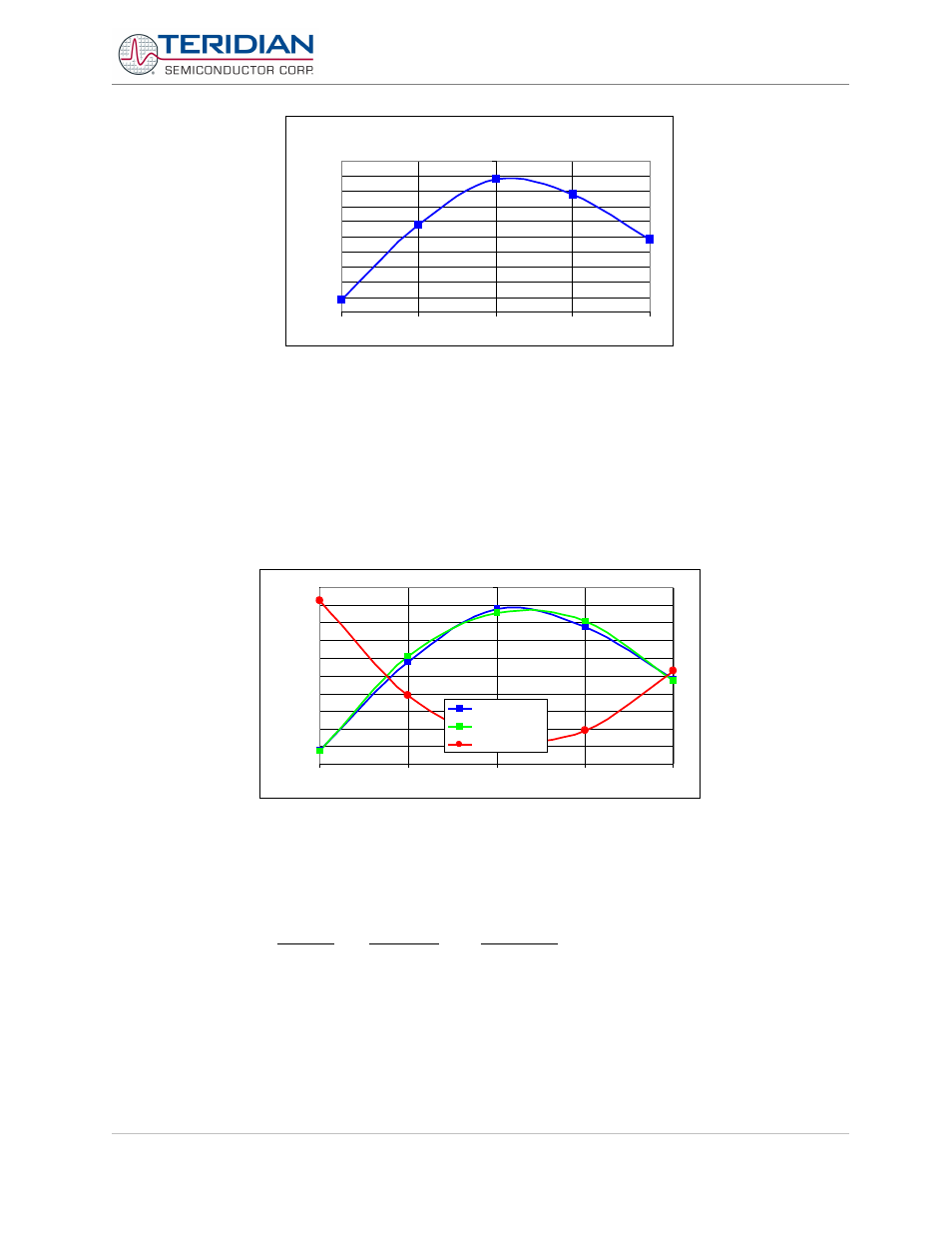
Figure 5-24: Crystal Frequency over Temperature
One method to correct the temperature characteristics of the crystal is to obtain coefficients from the curve in Figure
31 by curve-fitting the PPM deviations A fairly close curve fit is achieved with the coefficients a = 10.89, b = 0.122, and
c = –0.00714 (see Figure 32).
f = f
nom
* (1 + a/10
6
+ T * b/10
6
+ T2* c/10
6
)
When applying the inverted coefficients, a curve (see Figure 5-25) will result that effectively neutralizes the original
crystal characteristics.
32767.5
32767.6
32767.7
32767.8
32767.9
32768
32768.1
32768.2
32768.3
32768.4
32768.5
-50
-25
0
25
50
crystal
curve fit
inverse curve
Figure 5-25: Crystal Compensation
The MPU Demo Code supplied with the TERIDIAN Demo Kits has a direct interface for these coefficients and it
directly controls the RTC_DEC_SEC or RTC_INC_SEC registers. This interface is implemented by the MPU variables
Y_CAL, Y_CALC, and Y_CALC2 (MPU addresses 0x04, 0x05, 0x06). For the Demo Code, the coefficients have to be
entered in the form:
1000
2
_
100
_
10
_
)
(
2
CALC
Y
T
CALC
Y
T
CAL
Y
ppm
CORRECTION
⋅
+
⋅
+
=
Note that the coefficients are scaled by 10, 100, and 1000 to provide more resolution. For our example case, the
coefficients would then become (after rounding):
Y_CAL = 109, Y_CALC = 12, Y_CALC2 = 7
Alternatively, the mains frequency may be used to stabilize or check the function of the RTC. For this purpose, the CE
provides a count of the zero crossings detected for the selected line voltage in the MAIN_EDGE_X address. This
count is equivalent to twice the line frequency, and can be used to synchronize and/or correct the RTC.
Revision 2.4
TERIDIAN Proprietary
82 of 137
© Copyright 2005-2006 TERIDIAN Semiconductor Corporation