Interrupt priority level structure – Maxim Integrated 71M6513H Power Meter IC Family Software User Manual
Page 129
71M651x Software User’s Guide
6.3.5.3. Interrupt Priority Level Structure
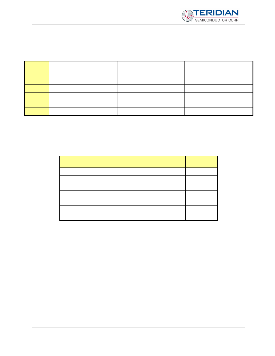
All interrupt sources are combined in groups:
group
0
External interrupt 0
Serial channel 1 interrupt
1
Timer 0 interrupt
-
External interrupt 2
2
External interrupt 1
-
External interrupt 3
3
Timer 1 interrupt
-
External interrupt 4
4
Serial channel 0 interrupt
-
External interrupt 5
5
-
-
External interrupt 6
Table 6-51: Priority Level Groups
Each group of interrupt sources can be programmed individually to one of four priority levels by setting or clearing one
bit in the special function register IP0 and one in IP1.
If requests of the same priority level are received simultane-
ously, an internal polling sequence determines which request is serviced first.
The functionality of the external interrupts is described in Table 6-51.
External
Interrupt
Connection
Polarity
Flag Reset
0
Digital I/O High Priority
see DIO_Rx
automatic
1
Digital I/O Low Priority
see DIO_Rx
automatic
2
Comparator
falling
automatic
3
CE_BUSY
falling
automatic
4
Comparator
rising
automatic
5
EEPROM busy
falling
automatic
6
XFER_BUSY OR RTC_1SEC
falling
manual
Table 6-52: External MPU Interrupts
Revision 2.4
TERIDIAN Proprietary
129 of 137
© Copyright 2005-2006 TERIDIAN Semiconductor Corporation