Maxim Integrated 71M6513H Power Meter IC Family Software User Manual
Page 121
71M651x Software User’s Guide
Mode A
This mode is similar to Mode 2 and 3 of serial interface 0. 11 bits are transmitted or received: a start bit (0), 8 data bits
(LSB first), a programmable 9th bit, and a stop bit (1). The 9th bit can be used to control the parity of the serial
interface: at transmission, bit tb81 in S1CON is output as the 9th bit, and at receive, the 9th bit affects rb81 in the
Special Function Register S1CON. The only difference between Mode 3 and A is that in Mode A, only the internal
baud rate generator can be used to specify the baud rate.
Mode B
This mode is similar to Mode 1 of serial interface 0. Pin rxd1 serves as an input, and txd1 serves as a serial output. No
external shift clock is used. 10 bits are transmitted: a start bit (always 0), 8 data bits (LSB first), and a stop bit (always
1). On receive, a start bit synchronizes the transmission. 8 data bits are available by reading S1BUF, and the stop bit
sets the flag rb81 in the Special Function Register S1CON. In mode B, the internal baud rate generator specifies the
baud rate.
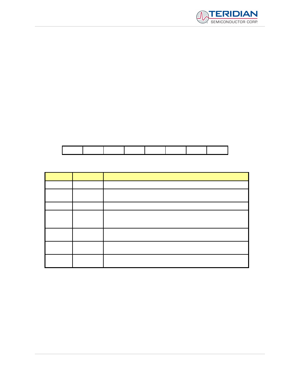
Serial Interface 1 Control Register (S1CON).
The function of the serial port depends on the setting of the Serial Port Control Register S1CON.
MSB
LSB
sm
-
sm21
REN1
tb81
rb81
ti1
ri1
Table 6-31: The S1CON Register
Bit
Symbol
Function
S1CON.7
sm
Sets baud rate
S1CON.5
sm21
Enables the multiprocessor communication feature (see description
above).
S1CON.4
REN1
If set, enables serial reception. Cleared by software to disable reception.
S1CON.3
Tb81
The 9
th
transmitted data bit in Mode A. Set or cleared by the MPU,
depending on the function it performs (parity check, multiprocessor
communication etc.)
S1CON.2
Rb81
In Modes 2 and 3, it is the 9
th
data bit received. In Mode B, if sm21 is 0,
rb81 is the stop bit. Must be cleared by software
S1CON.1
ti1
Transmit interrupt flag, set by hardware after completion of a serial
transfer. Must be cleared by software.
S1CON.0
ri1
Receive interrupt flag, set by hardware after completion of a serial
reception. Must be cleared by software
Table 6-32: The S1CON Bit Functions
Revision 2.4
TERIDIAN Proprietary
121 of 137
© Copyright 2005-2006 TERIDIAN Semiconductor Corporation