Timer/counter mode control register (tmod), Timer/counter control register (tcon) – Maxim Integrated 71M6513H Power Meter IC Family Software User Manual
Page 117
71M651x Software User’s Guide
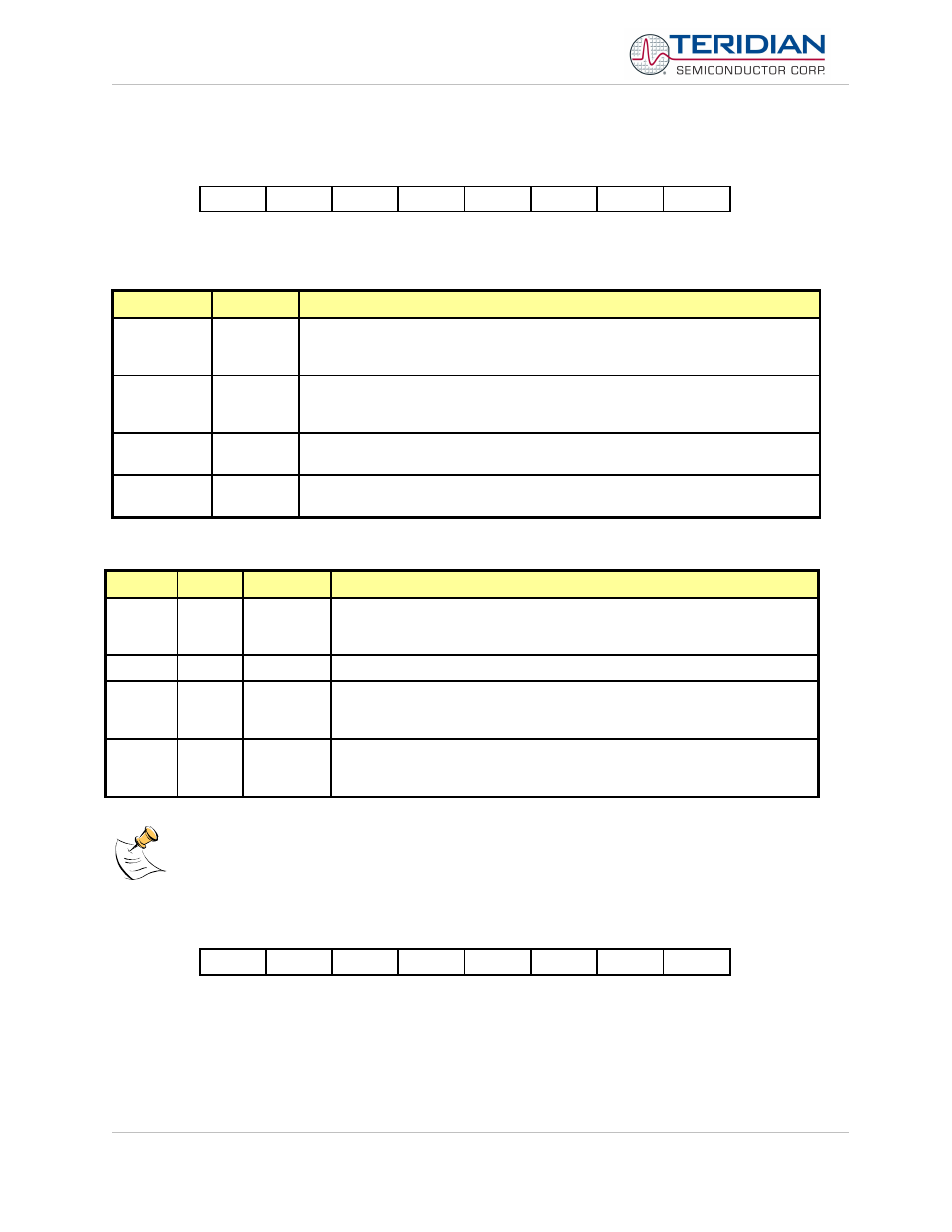
Timer/Counter Mode Control Register (TMOD)
MSB
LSB
GATE
C/T
M1
M0
GATE
C/T
M1
M0
Timer 1
Timer 0
Table 6-20: The TMOD Register
Bit
Symbol
Function
TMOD.7
TMOD.3
Gate
If set, enables external gate control (pin int0 or int1 for Counter 0 or 1,
respectively). When int0 or int1 is high, and trx bit is set (see TCON register), a
counter is incremented every falling edge on t0 or t1 input pin
TMOD.6
TMOD.2
C/T
Selects Timer or Counter operation. When set to 1, a Counter operation is
performed. When cleared to 0, the corresponding register will function as a
Timer.
TMOD.5
TMOD.1
M1
Selects the mode for Timer/Counter 0 or Timer/Counter 1, as shown in TMOD
description.
TMOD.4
TMOD.0
M0
Selects the mode for Timer/Counter 0 or Timer/Counter 1, as shown in TMOD
description.
Table 6-21: The TMOD Register Bits Description
M1
M0
Mode
Function
0
0
Mode 0
13-bit Counter/Timer with 5 lower bits in the TL0 or TL1 register and the
remaining 8 bits in the TH0 or TH1 register (for Timer 0 and Timer 1,
respectively). The 3 high order bits of TL0 and TL1 are held at zero.
0
1
Mode 1
16-bit Counter/Timer.
1
0
Mode2
8-bit auto-reload Counter/Timer. The reload value is kept in TH0 or TH1,
while TL0 or TL1 is incremented every machine cycle. When tl(x)
overflows, a value from th(x) is copied to tl(x).
1
1
Mode3
If Timer 1 m1 and m0 bits are set to '1', Timer 1 stops. If Timer 0 m1 and
m0 bits are set to '1', Timer 0 acts as two independent 8 bit
Timer/Counters.
Table 6-22: Timers/Counters Mode Description
TL0 is affected by tr0 and gate control bits, and sets TF0 flag on overflow.
TH0 is affected by tr1 bit, and sets TF1 flag on overflow.
Timer/Counter Control Register (TCON)
MSB
LSB
TF1
TR1
TF0
TR0
IE1
IT1
IE0
IT0
Table 6-23: The TCON Register
Revision 2.4
TERIDIAN Proprietary
117 of 137
© Copyright 2005-2006 TERIDIAN Semiconductor Corporation