Maxim Integrated 71M6513H Power Meter IC Family Software User Manual
Page 74
71M651x Software User’s Guide
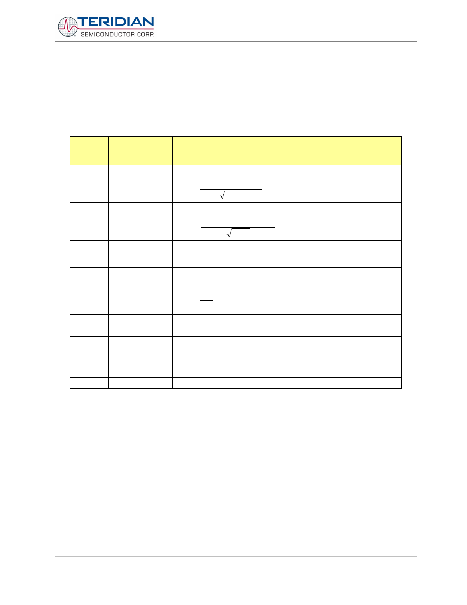
MPU INSTANTANEOUS OUTPUT VARIABLES
The Demo Code processes CE outputs after each accumulation interval. It calculates instantaneous values such as
VRMS, IRMS, W and VA as well as accumulated values such as Wh, VARh, and VAh. Table 5-7 lists the calculated
instantaneous values for single-phase ICs.
Accumulated values are calculated by summing the CE XFER outputs into 64-bit variables. Thus, the accumulators
will hold at least 136 years of data when XFER rate is 1Hz. The values calculated by the MPU are in XRAM according
to Table 5-10. Table 5-8 lists the calculated instantaneous values for poly-phase ICs.
XRAM
Word
Address
Name
Description
0x14
0x15
0x16
Vrms_A
reserved
reserved
Vrms:
Nacc
VMAX
LSB
8
10
7610
.
3
−
⋅
=
0x17
0x18
0x19
Irms_A
Irms_B
reserved
Irms from element 0, 1, 2.
Nacc
In
IMAX
LSB
8
10
7610
.
3
8
−
⋅
=
0x1A
0x1B
0x1C
IPhase_A
reserved
reserved
Phase between voltage and current. The number of degrees I lags V.
LSB=0.001°, range: 0…+360
0x1D
Frequency
Frequency of the voltage signal selected by the CE input. If the selected
voltage is below the sag threshold, Frequency = 0.
LSB
6
32
10
587
.
0
2
−
⋅
≈
≡
S
F
Hz
0x1E
Delta_T
Deviation from Calibration temperature.
LSB = 0.1
0
C.
0x1F
0x20
reserved
reserved
0x21
Status
MPU Status Word
0x22
OperatingTime
Total operating time. LSB = 0.01h = 36s
0x23
Reserved
Table 5-6: MPU Instantaneous Output Variables (6511)
Revision 2.4
TERIDIAN Proprietary
74 of 137
© Copyright 2005-2006 TERIDIAN Semiconductor Corporation