Maxim Integrated 71M6513H Power Meter IC Family Software User Manual
Page 14
71M651x Software User’s Guide
In order to generate and test software, the Keil compiler and the Signum in-circuit emulator (ICE) must be installed per
the instructions in section 4. The include files and header files must also be present on the development PC. Typically,
a design session consists of the following steps:
•
Editing C source code using µVision2
•
Compiling the source code using the Keil compiler
•
Modifying the source code and recompiling until all compiler error messages are resolved
•
Using the assembler and linker to generate executable code
•
Downloading the executable code to the ICE
•
Executing the code and watching its effects on the target
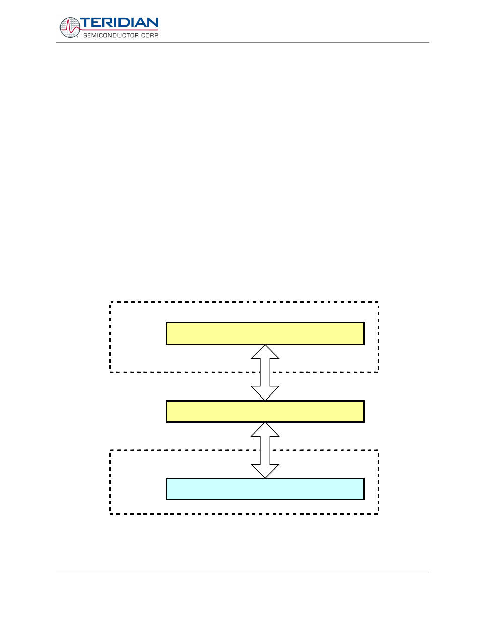
Software Architecture:
The 71M651x software architecture is partitioned into three separate layers:
1.
The lowest level is the device or hardware layer, i.e. the discrete functional blocks of the chip and the
peripheral components, such as RTC, EEPROM, MPU clock management, LCD etc.
2.
The second layer consists of the functions, which enable the application to communicate with the device
layer.
3.
The third layer is the application layer. This layer is partially implemented by the Demo Code for evaluation
purposes, but extensions and enhancements can be added by the application software developer to design
suitable electronic power meter applications.
Figure 1 shows the partitions of each software component. As illustrated, there are many different designs an
application can develop depending on its usage. Section 5 describes in more detail the functions within each
component.
Figure 2-1: Software Structure
Revision 2.4
TERIDIAN Proprietary
14 of 137
© Copyright 2005-2006 TERIDIAN Semiconductor Corporation
Application
Layer
Device
Layer
Application
Functions
Hardware