Maxim Integrated 71M6513H Power Meter IC Family Software User Manual
Page 23
71M651x Software User’s Guide
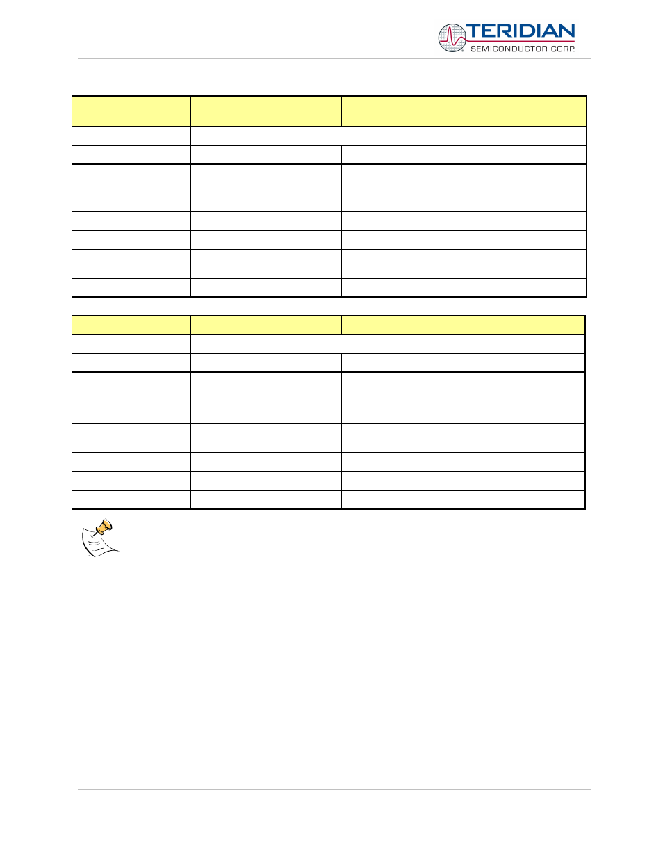
C
COMPUTE ENGINE, TMUX,
and RTM CONTROL
Description:
Allows the user to enable and configure the compute engine plus other controls
Usage:
C [option] [argument]
Options:
En
Compute Engine Enable (1 Enable,
0 Disable)
Tn
Select input n for TMUX output pin
REn
RTM output control (1 Enable, 0 Disable)
RSa.b.c.d
Selects RTM output
Example:
CE0
Disables CE, followed by “CE OFF” display on LCD.
The Demo Code will reset if the WD timer is enabled.
CT3
Selects VBIAS for TMUX output pin
CL
CALIBRATION CONTROL
Description:
Allows the user to initiate auto-calibration and to store calibration values.
Usage:
CL [option]
Options:
B
Begin auto-calibration. Prior to auto-calibration, the
calibration coefficients are automatically restored
from flash memory. If the coefficients are not unity
gain (0x4000), auto-calibration will yield poor results.
S
Save calibration coefficients to EEPROM starting at
address 0x0004
R
Restore calibration coefficients from EEPROM
D
Restore coefficients from flash memory
Example:
CLB
Starts auto-calibration
Before starting the auto-calibration process, target values for voltage and current must be entered in I/O
RAM prior to calibration (V at 0x2029, I at 0x202A, duration in accumulation intervals at 0x2028), and the
target voltage and current must be applied constantly during calibration. No phase adjustment will be
performed. Coefficients can be saved to EEPROM using the CLS command.
Revision 2.4
TERIDIAN Proprietary
23 of 137
© Copyright 2005-2006 TERIDIAN Semiconductor Corporation