The interrupt service routine unit, Interrupt overview, Special function registers for interrupts – Maxim Integrated 71M6513H Power Meter IC Family Software User Manual
Page 126
71M651x Software User’s Guide
6.3.5. The Interrupt Service Routine Unit
The 80515 provides 11 interrupt sources with four priority levels. Each source has its own
request flag(s) located in a
special function register (TCON, IRCON, SCON).
Each interrupt requested by the corresponding flag can be
individually enabled or disabled by the enable bits in SFRs IEN0, IEN1, and IEN2.
6.3.5.1. Interrupt Overview
When an interrupt occurs, the MPU will vector to the predetermined address as shown in Table 6-58. Once interrupt
service has begun, it can be interrupted only by a higher priority interrupt. The interrupt service is terminated by a
return from instruction, "RETI". When a RETI instruction is performed, the processor will return to the instruction that
would have been next when the interrupt occurred.
When the interrupt condition occurs, the processor will also indicate this by setting a flag bit. This bit is set regardless
of whether the interrupt is enabled or disabled. Each interrupt flag is sampled once per machine cycle, then samples
are polled by the hardware. If the sample indicates a pending interrupt when the interrupt is enabled, then the interrupt
request flag is set. On the next instruction cycle, the interrupt will be acknowledged by hardware forcing an LCALL to
the appropriate vector address, if the following conditions are met:
•
No interrupt of equal or higher priority is already in progress.
•
An instruction is currently being executed and is not completed.
•
The instruction in progress is not RETI or any write access to the registers IEN0, IEN1, IEN2, IP0 or IP1.
Interrupt response will require a varying amount of time depending on the state of the microcontroller when the
interrupt occurs. If the microcontroller is performing an interrupt service with equal or greater priority, the new interrupt
will not be invoked. In other cases, the response time depends on the current instruction. The fastest possible
response to an interrupt is 7 machine cycles. This includes one machine cycle for detecting the interrupt and six
cycles to perform the LCALL.
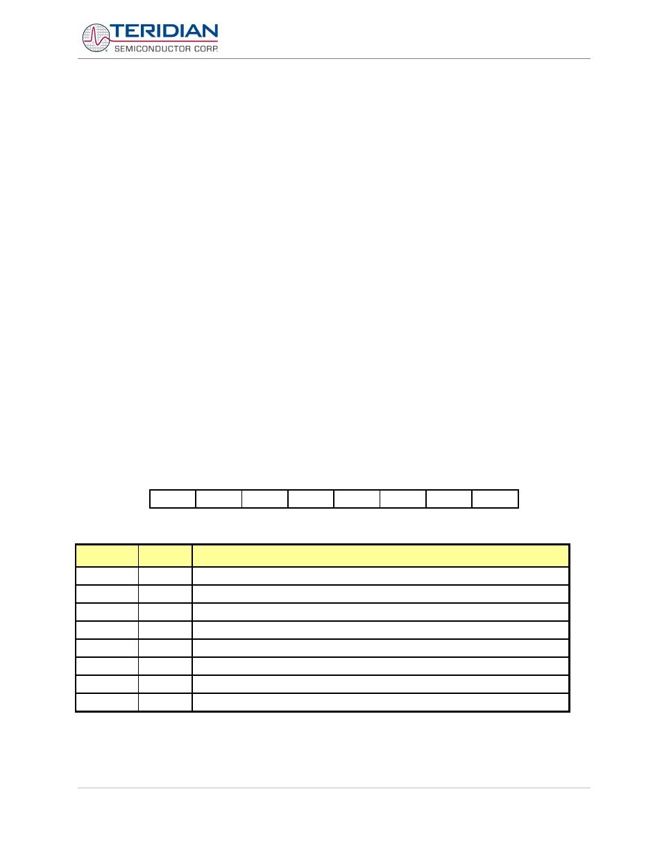
6.3.5.2. Special Function Registers for Interrupts
Interrupt Enable 0 Register (ie0)
MSB
LSB
eal
wdt
es0
et1
ex1
et0
ex0
Table 6-41: The IEN0 Register
Bit
Symbol
Function
IEN0.7
eal
eal=0 – disable all interrupts
IEN0.6
wdt
Not used for interrupt control
IEN0.5
-
IEN0.4
es0
es0=0 – disable serial channel 0 interrupt
IEN0.3
et1
et1=0 – disable timer 1 overflow interrupt
IEN0.2
ex1
ex1=0 – disable external interrupt 1
IEN0.1
et0
et0=0 – disable timer 0 overflow interrupt
IEN0.0
ex0
ex0=0 – disable external interrupt 0
Table 6-42: The IEN0 Bit Functions
Revision 2.4
TERIDIAN Proprietary
126 of 137
© Copyright 2005-2006 TERIDIAN Semiconductor Corporation