Design reference, Program memory, Data memory – Maxim Integrated 71M6513H Power Meter IC Family Software User Manual
Page 17: Program memory 3.2. data memory
71M651x Software User’s Guide
3. DESIGN REFERENCE
As depicted in Figure 1 of section 2, the 71M651x provides a great deal of design flexibility for the application de-
veloper. Programming details are described below.
3.1.PROGRAM MEMORY
The embedded 80515 MPU within the 71M651x has separate program (64K bytes) and data memory (2K bytes). In
addition, it has 4K bytes of Compute Engine program RAM.
The Flash program memory is addressed as a 64KB block, segmented in 512-byte pages. Selection of these
individual blocks is accomplished using the function calls related to flash memory, which are described in more detail
below.
When generating code for ROM applications, special precautions have to be taken. Contact TERIDIAN
Semiconductor for details.
3.2.DATA MEMORY
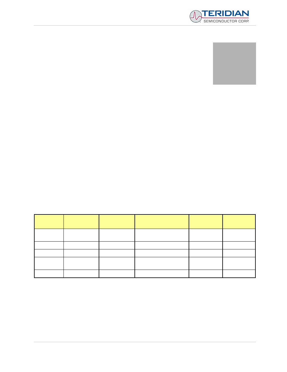
The 71M651x has 2K bytes of Data Memory for exclusive use of the embedded 80C515 MPU. In addition, there are
5K byte shared with the Compute Engine. See Table 3-1 for a summary.
Address
(hex)
Memory
Technology
Memory Type
Typical Usage
Wait States
(at 5MHz)
Memory Size
(bytes)
0000-FFFF
Flash Memory
Non-volatile
Program and non-volatile
data
0
64KB
0000-07FF
Static RAM
Battery-buffered
MPU data XRAM,
0
2KB
1000-13FF
Static RAM
Volatile
CE data
5
1KB
2000-20FF
Static RAM
Volatile
Miscellaneous I/O RAM
(configuration RAM)
0
256
3000-3FFF
Static RAM
Volatile
CE Program code
5
4KB
Table 3-1: Memory Map
Revision 2.4
TERIDIAN Proprietary
17 of 137
© Copyright 2005-2006 TERIDIAN Semiconductor Corporation
3