Maxim Integrated 71M6513H Power Meter IC Family Software User Manual
Page 26
71M651x Software User’s Guide
MR
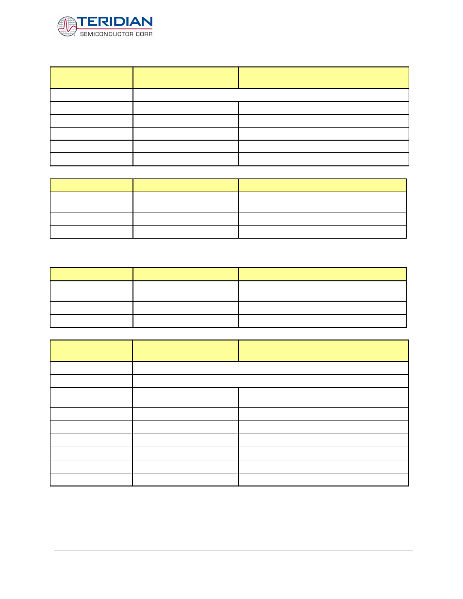
RMS DISPLAY CONTROL
(LCD)
Description:
Allows user to select meter RMS display for voltage or current.
Usage:
MR [option]. [option]
Options:
1. [phase]
Displays instantaneous RMS current
2. [phase]
Displays instantaneous RMS voltage
Values for [phase]: 1 = A, 2 = B, 3 = C
Example:
MR1.1
Displays phase A RMS current.
P
PROFILE OF METER
Description:
Returns current meter
configuration profile
Usage:
P
Options:
None
The profile of the meter is a summary of the important settings of the I/O RAM registers.
PS
POWER SAVE MODE
Description:
Enters power save mode
Disables CE, ADC, CKOUT, ECK, RTM, SSI, TMUX
VREF, and serial port, sets MPU clock to 38.4KHz.
Usage:
PS
Options:
None
R
USER I/O AND SFR
CONTROL
Description:
Allows user to read and write to I / O RAM and special function registers.
Usage:
R [option] [register] … [option]
Options:
Ix…
Select I/O RAM location x ($2000 offset is
automatically added)
x…
Select internal SFR at address x
..???..
Read consecutive registers in Decimal
..$$$..
Read consecutive registers in Hex
..=n=n..
Set consecutive registers' values
;
Exit SFR controls
Example:
RI0$$$
Read CE0, CE1 and CE2 registers
Revision 2.4
TERIDIAN Proprietary
26 of 137
© Copyright 2005-2006 TERIDIAN Semiconductor Corporation