Special function registers for the wd timer – Maxim Integrated 71M6513H Power Meter IC Family Software User Manual
Page 124
71M651x Software User’s Guide
second instruction sets swdt. The maximum delay allowed between setting wdt and swdt is 12 clock cycles. If this
period has expired and swdt has not been set, the WDT is automatically reset, otherwise the watchdog timer is
reloaded with the content of the WDTREL register and wdt is automatically reset.
Since the WDT requires exact timing, firmware needs to be designed with special care in order to avoid
unwanted WDT resets. TERIDIAN strongly discourages the use of the software WDT.
Special Function Registers for the WD Timer
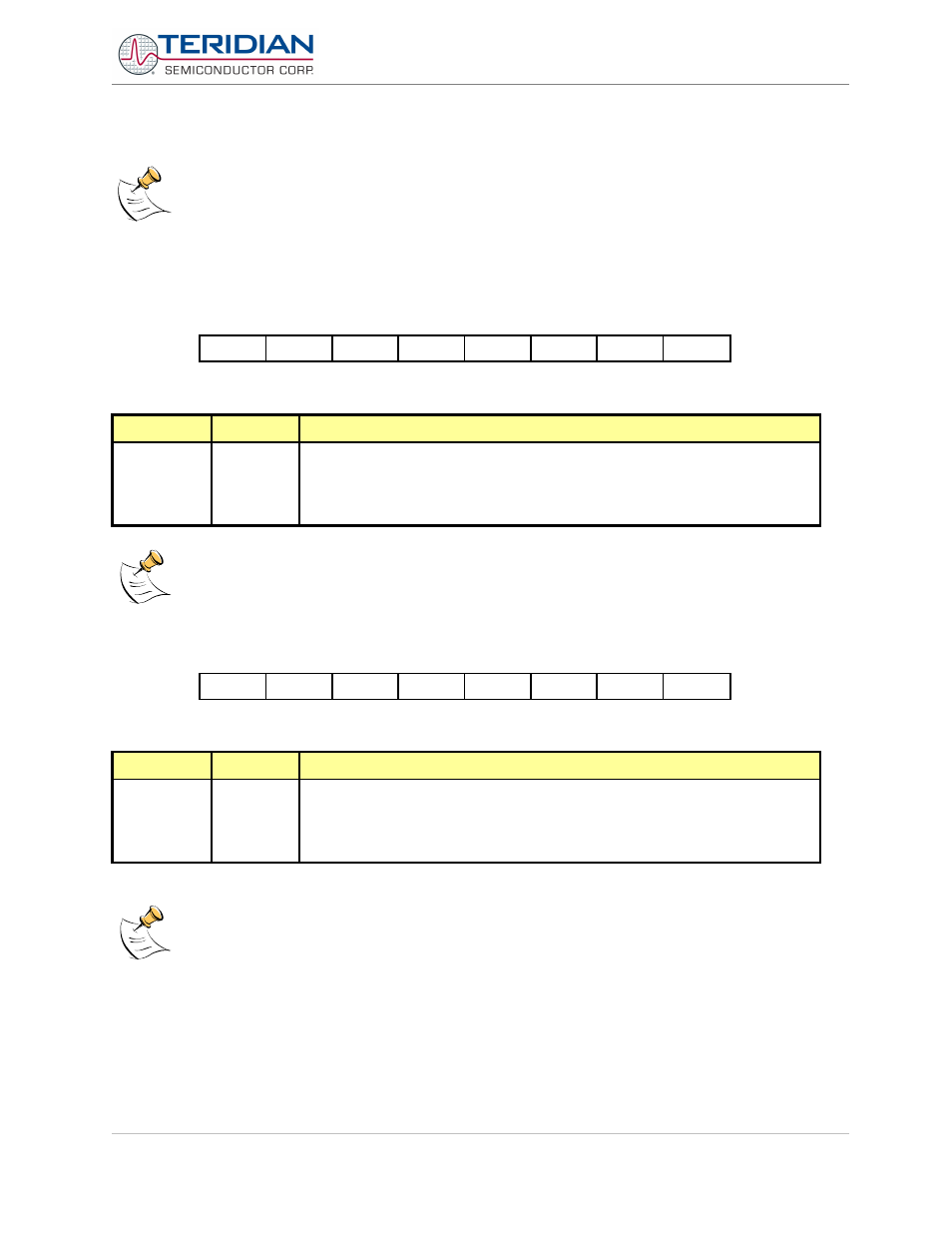
Interrupt Enable 0 Register (IEN0):
MSB
LSB
eal
wdt
et2
es0
et1
ex1
et0
ex0
Table 6-33: The IEN0 Register
Bit
Symbol
Function
IEN0.6
wdt
Watchdog timer refresh flag.
Set to initiate a refresh of the watchdog timer. Must be set directly before swdt is
set to prevent an unintentional refresh of the watchdog timer. Wdt is reset by
hardware 12 clock cycles after it has been set.
Table 6-34: The IEN0 Bit Functions
The remaining bits in the IEN0 register are not used for watchdog control
Interrupt Enable 1 Register (IEN1):
MSB
LSB
exen2
swdt
ex6
ex5
ex4
ex3
ex2
Table 6-35: The IEN1 Register
Bit
Symbol
Function
IEN1.6
swdt
Watchdog timer start/refresh flag.
Set to activate/refresh the watchdog timer. When directly set after setting wdt, a
watchdog timer refresh is performed. Bit swdt is reset by the hardware 12 clock
cycles after it has been set.
Table 6-36: The IEN1 Bit Functions
The remaining bits in the IEN1 register are not used for watchdog control
Revision 2.4
TERIDIAN Proprietary
124 of 137
© Copyright 2005-2006 TERIDIAN Semiconductor Corporation