Basic code architecture, Initialization, Foreground – Maxim Integrated 71M6513H Power Meter IC Family Software User Manual
Page 47: Timer interrupt
71M651x Software User’s Guide
C_START, which is contained in the second startup assembly program named init.A51 (Keil/C51/LIB directory, see
Figure 5-3). Init.A51 finally causes the jump to main(). The startup files are described in section 5.7.
The stack is located at 0x80, growing to higher values, while the reentrant stack is located at 0xFF, growing down-
wards.
Once operating, the main() program expects regular interrupts from the CE. If no interrupts occur, the main() program
will cease to trigger the watchdog timer, resulting in a reset condition, if the watchdog timer is enabled.
5.3.BASIC CODE ARCHITECTURE
The TERIDIAN 71M651x firmware can be divided into two code parts. One is the Background task that is executed
whenever there are no other higher priority exceptions such as the servicing of interrupts. The second part consists of
the interrupt-driven code (Foreground) tasks, such as the CE_BUSY Interrupt, Timer Interrupt, and other Interrupt
service routines. The background code takes care of the non time-critical functions starting with the system reset, and
this code is executed every time when there are CPU resources available after taking care of all interrupt-driven tasks.
The background of the 71M651x firmware is implemented as a very simple state machine. One state is serving the
command inputs and the other is idle/Display control.
5.3.1. Initialization
When the power applied for the first time or RESETZ is asserted, the 71M651x device executes the code pointed to
by the reset vector.
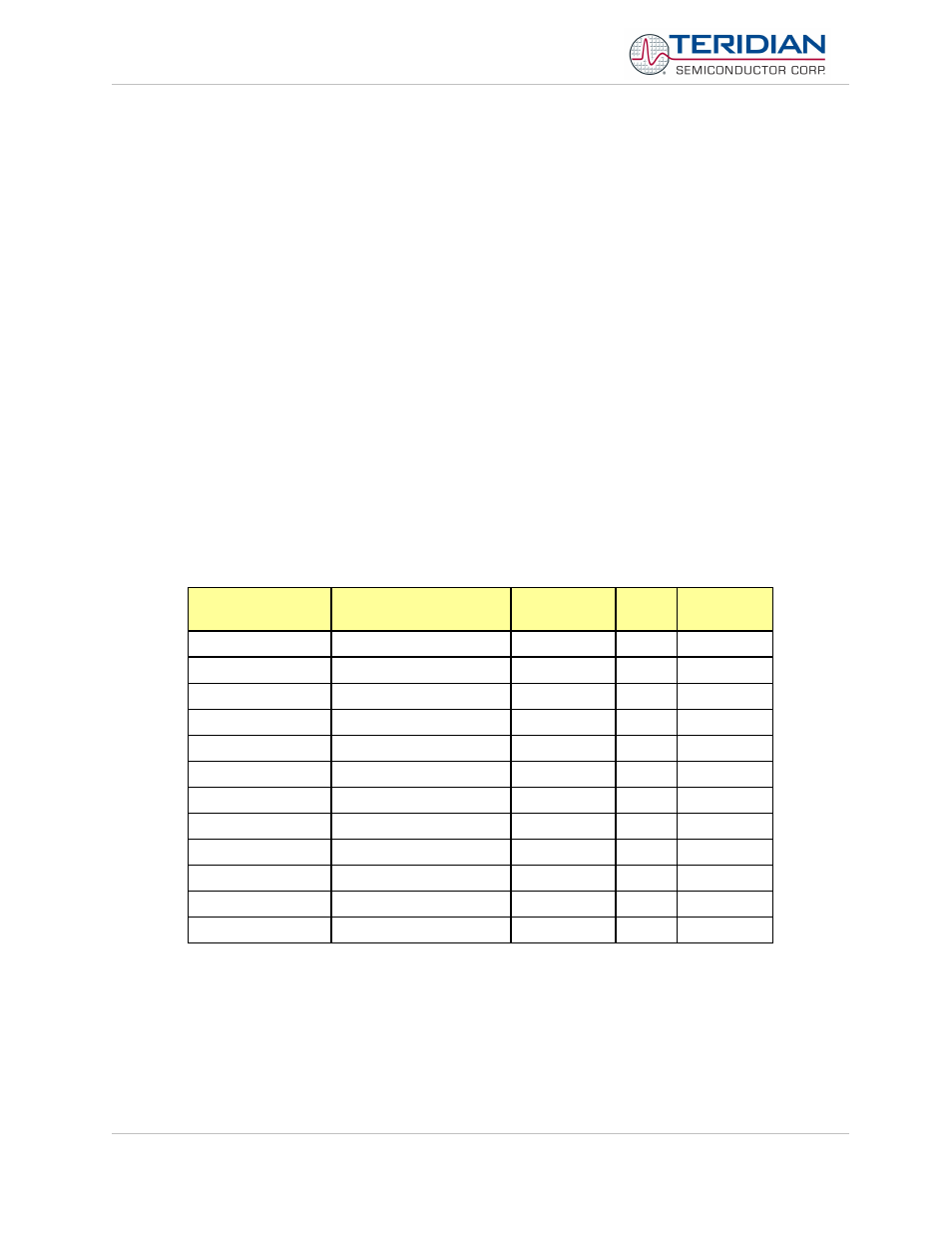
5.3.2. Foreground
There are total 12 interrupts available for the 80515, and the revision 3.04 demo code uses a total of 11 interrupts.
Table 5-2 shows the interrupt service routines (ISRs), the corresponding vectors (Table 6-58 in section 6.3.5.4) and
their priority, as assigned by the MPU using the IP0 and IP1 registers (see section 6.3.5.2).
Interrupt Routine
name
in source file
vector
priority (3 =
highest)
io_high_priority_isr
EXT0
misc.c
0x03
1
io_low_priority_isr
EXT1
misc.c
0x13
3
compare_falling_isr
EXT2
io651x.c
0x4B
0
ce_busy_isr
EXT3
ce.c
0x53
3
compare_rising_isr
EXT4
io651x.c
0x5B
0
eeprom_isr
EXT5
eeprom.c
0x63
1
xfer_busy_isr
EXT6 (shared w/ RTC)
ce.c
0x6B
2
timer0_isr
timers.c
0x0B
0
timer1_isr
timers.c
0x1B
0
rtc_isr
EXT6 (shared w/ XFER)
rtc.c
0x6B
2
es0_isr
serial.c
0x23
1
es1_isr
serial.c
0x83
1
Table 5-2: Interrupt Service Routines
All interrupt service routines (ISRs) must be declared “small reentrant”. Also, all routines called by ISRs must be re-
entrant as well.
TIMER Interrupt
timer0 of the MPU is used to generate a 10ms timer tick, which is adjusted for MPU clock speed. The timer tick
(variable tick_tock) is used to control the software timers. The software timers are updated by the process_timers()
Revision 2.4
TERIDIAN Proprietary
47 of 137
© Copyright 2005-2006 TERIDIAN Semiconductor Corporation